THS – FI022GB2K8v3 --- V - MAINTENANCE
35
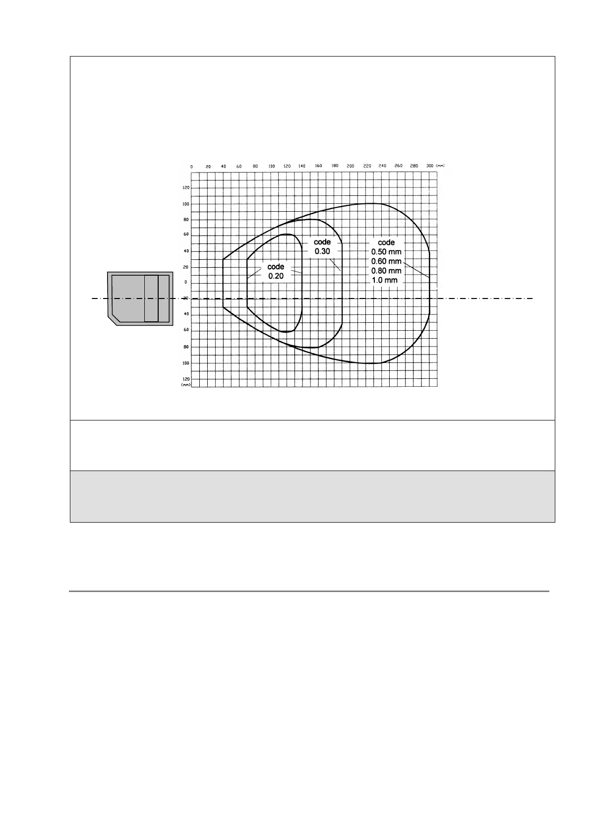
Reading field width depends on the distance between the label and the reader.
The following figure gives the reading diagram for the following conditions::
• code = interleaved 2/5 or code 39
• PCS = 0.90
• P angle = 0°
• S angle = 10°
• T angle = 0°
Fig. II -34 width of the reading field
For example, for a code 50 mm wide moving through at 1500mm/s at a distance from the reader corresponding to a
reading field of 200mm, we get:
SS = (((200-50) /1500) * 350) - 2 = 33 effective scans
The position of the reader must therefore be chosen so that FW is at maximum, based on the reading diagram, and LW e
LS should be chosen so that
(FW-LW)/LS > 0.02
Kit installation procedure
1. Mechanical mounting, including determination of:
• Distance between reader and metal detector probe
• code transit speed
• label dimensions
2. Electrical connection to the ALM card
3. Assignment of the CEIA enabling code to parameter BE
4. Selection of parameters from the "barcode reader" menu
5. Selection of the corresponding product type, or creation of a new one if necessary
6. Execution of barcode acquisition procedure (command LC)
7. Repetition of steps 5 and 6 for all products being used
Distance of the label
from the reader axis
reader axis
Reader - label distance