THS – FI022GB2K8v3 --- V - MAINTENANCE
24
Conveyor belt
The distances quoted below are indicative only, and subject to variation according to the sensitivity required and to the
type of probe. When installation has been completed, therefore, correct operation should be checked.
Load-bearing structure of the conveyor belt
The load-bearing structures of the conveyor belt must be stable and not subject
to detectable vibration during movement of the belt.
THS/M
The structure of the belt must be in non-magnetic steel
(e.g. non-magnetic AISI
304).
Fig. II-13 Load-bearing structure
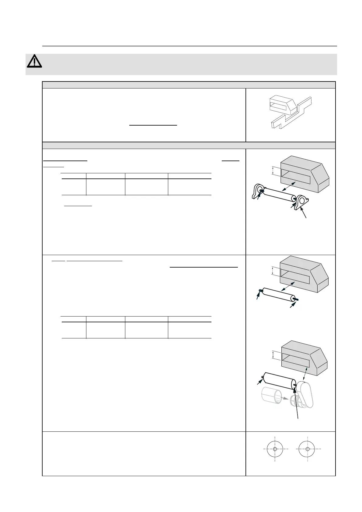
Rollers of the conveyor belt
In general, it is advisable that any rollers located near the antenna be of
insulating material. In which case, there must be an electrical connection on only
one side of the roller, in order to allow the discharge of any electrostatic charges.
| Model THS/M THS/A Other models |
| |
| D ≥ 3 DH * ≥ 3 DH * ≥ 1,5 DH ** |
| |
* use nonmagnetic steel bearings.
** plastic roller with fixed nonmagnetic steel axle and nonmagnetic steel bearings.
N.B.: the bearings must be placed at the ends of the rollers, never in the middle.
I
C
D
B
DH
Fig. II-14. Rollers in insulating
material with metallic
bearings
I: insulated support
C: non-insulated support; B: bearing
Metal rollers , pulling or free, must be located at a distance D, to both sides of
the antenna. Such rollers must also be insulated on a single supporting piece
in
order to avoid forming electromagnetic coils and allow the discharge of any
electrostatic charges.
| Model THS/M THS/A Other models |
| |
| D ≥ 6 DH ≥ 4 DH * ≥ 2 DH |
| |
C: non-insulated support
I: insulated support
S: screening
I
C
D
DH
Fig. II-15a. Free metal rollers
I: insulated support C: non-
insulated support
I
C
D
S
DH
Fig. II-15b. Pulling metal rollers
Metal rollers must be perfectly concentric.
YES! NO!
Fig. II-16