THS – FI022GB2K8v3 --- V - MAINTENANCE
25
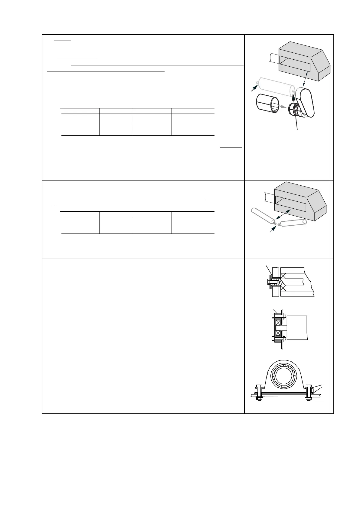
The motors
must be located at a distance D from the antenna, adopting measures
identical to those described for the rollers above.
Fit electrical motors
with special iron screens and mains filters of sufficient
capacity. It is recommended that motors running on alternating current be used
rather than those running on continuous current. The table that follows provides
some general guidelines for the distances to be placed between the probe and
asynchronous motors, depending on their power
Minimum distance advisable between the probe and motors with alternating
current (without motor screening)
| Models THS/M THS/A Other models |
| |
| D 0,5 CV ≥ 5 DH ≥ 5 DH ≥ 3 DH |
| 1 CV ≥ 6 DH ≥ 6 DH ≥ 4 DH |
| |
• In the immediate proximity of the metal detector, the motors may be screened
by means of cylindrical enveloping in iron; such cylinders must have a
sufficiently large diameter to contain the motors and a thickness of not less
than 2 mm. The cylinders must be of the unwelded type
• The table indicates distance measurements corresponding to a high
sensitivity level; for lower sensitivity levels, distance D may be reduced.
I
C
D
S
DH
Fig. II-17. motors
C: non-insulated support
I: insulated support
S: screening
Attention: Rollers for V-shaped belts, if attached to the frame on one side
only, do not require the insulation of the pin.
As in the preceding case, their distance from the probe must be at least equal to
D, to both sides of the antenna
| Models THS/M THS/A Other models |
| |
| D ≥ 9 DH ≥ 6 DH ≥ 3 DH |
| |
D
C
DH
Fig. II-18. Metal rollers for V-
shaped belts
C: non-insulated support
Examples of roller insulation
Insulation of the pin of a roller.
I: ferrule in insulating material; P: side bulkhead of the belt frame;
R: roller.
I
P
R
Fig. II-19a
Insulation of the pin support of a roller.
I: bearing support in insulating material;
P: side bulkhead of the belt frame; R: roller.
I
P
R
Fig. II-19b
Insulation of the bearing support of a roller pin.
I: ferrule and spacer in insulating material.
I
Fig. II-19c
 Loading...