THS – FI022GB2K8v3 --- V - MAINTENANCE
33
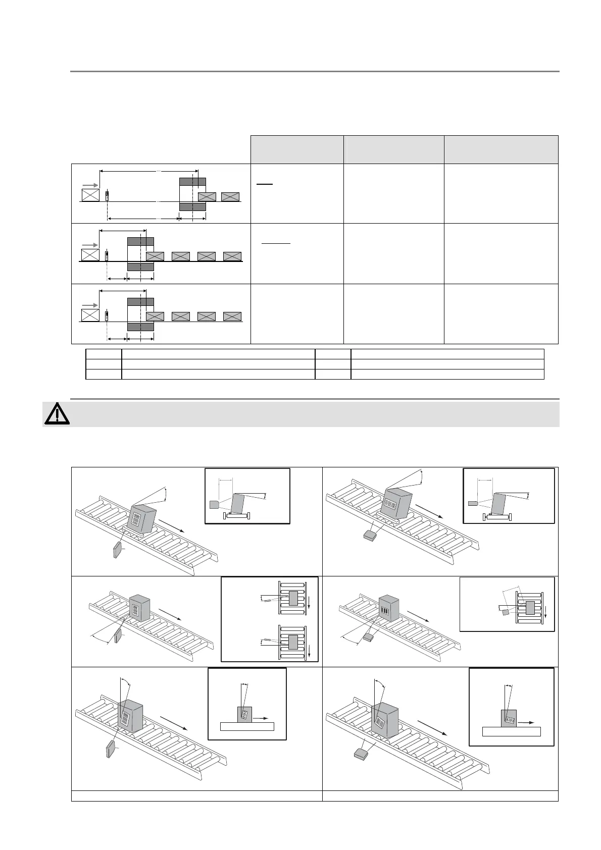
Distance between the reader and the metal detector probe and distance between packs
The reader is mounted upstream of the probe in order to read a code stamped on the pack. If the code is recognised, the
reader sends a command to the metal detector to select the relevant product type. The time required by the THS to
process the barcode is usually insignificant, but becomes important if the band is changed due to a modification in the
type of product.. When the metal detector receives the signal to change product type, an internal adjustment procedure is
activated the length of which determines the minimum distance between two packs with different codes, that is to say
containing different products.
Model / Event Distance between the
packs
Distance between the
barcode reader and the THS
probe
L
S
Dp
BR
N
D
sbr
THS/3F
with
change of band
(BA parameter)
between one product
and the other
D
p
≥ L + 3000 mm
D
sbr
≥ 3000 mm
L
S
D
p
BR
N
D
sbr
THS/3F
without change of
band (BA parameter)
between one product
and the other
D
p
≥ L + 300 mm
D
sbr
≥ 300 mm
L
S
D
p
BR
N
D
sbr
Other THS models
D
p
≥ L + 300 mm
D
sbr
≥ 300 mm
S
probe/electronics unit of the metal detector
L
length of probe
N
conveyor belt
Dsbr
Distance THS probe-barcode reader
BR
Barcode reader
Dp
Distance between the packs of different products
Position of the reader and the label in transit
A non-rigid mounting, using anti-vibration supports, should be adopted for the reader.
The two types of reader should be mounted as shown in the figures below.
Attention must be paid to the position of the pack in transit, in order to ensure that the barcode can be read (angles P, S
and T in the following figures).
P = 0˚
˜
P = 0˚
˜
D
P = 0˚
˜
P = 0˚
˜
D
S = 10 - 30˚
S = 10 - 30˚
S = 10 - 30˚
S = 10 - 30˚
S = 10 - 30˚
D
T = 0˚
˜
T = 0˚
˜
T = 0˚
˜
T = 0˚
˜
Fig. II-31a Step-Ladder reader: mounting Fig. II-31b Picket-Fence reader: mounting
 Loading...