THS – FI022GB2K8v3 --- V - MAINTENANCE
23
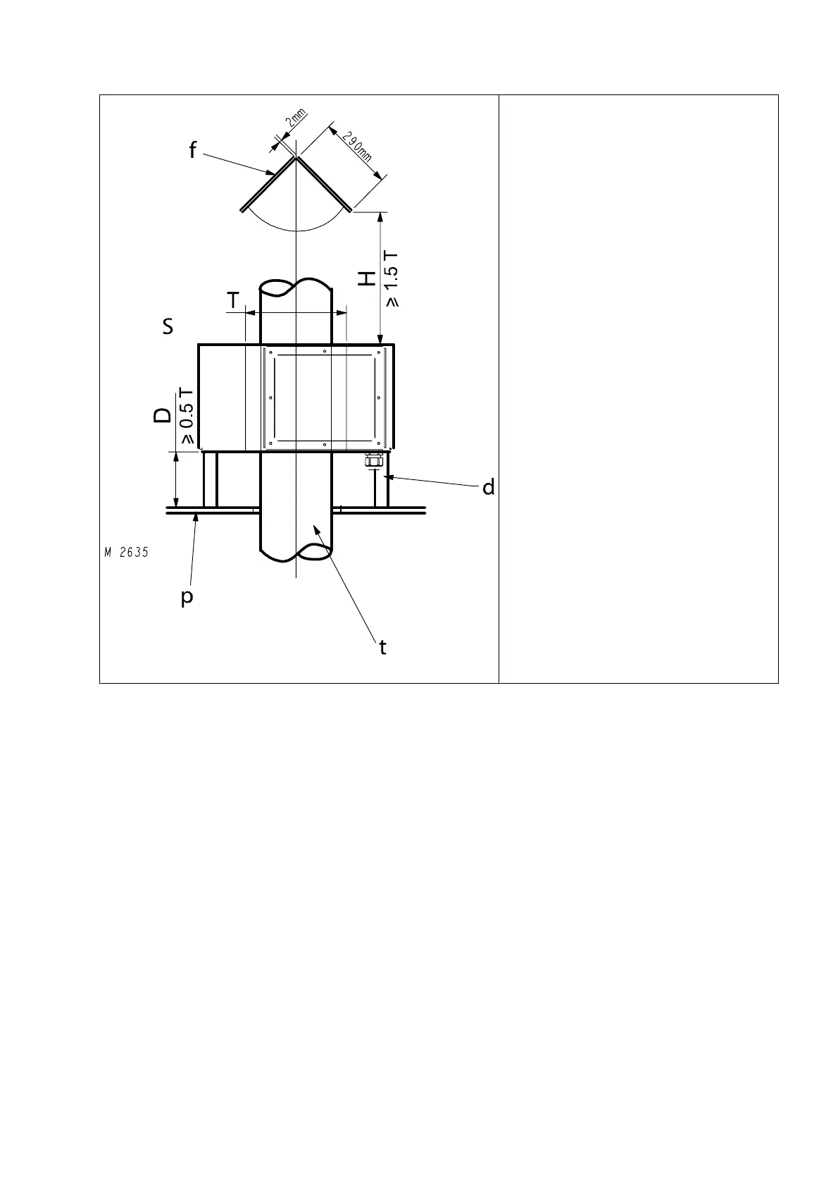
D: distance between probe S and support plate
P
d: rigid plastic spacer;
f: steel flap deflector (dim. 290x200x2mm);
H: distance between probe S and deflector f
p: stainless steel support plate;
S: probe.
T: diameter of the probe.
t: plastic pipe
Fig. II-12 – fixing the THS/G probe
THS/G : mounting the power supply unit
The power supply unit must be firmly fixed to the supporting structure with four screws, near the electronics unit and the
slave devices connected to the power supply unit (photocell, ejector etc.). For the location of the holes provided for fixing
the unit, see Figure I-14a.



 To Next Page