THS – FI022GB2K8v3 --- V - MAINTENANCE
17
• Load-bearing structure
During assembly the solidity of the load-bearing structure should be borne in mind, in order to ensure that
the detector does not oscillate, causing false alarms
• Metal structures surrounding the Metal Detector/conveyor belt system
Fixed metal structures
All the fixed metallic structures in proximity to the detector must be securely
fastened down with bolts and self-blocking nuts and, if they form intermittent
loops, soldered.
This is due to the fact that sporadic metallic contacts due to vibrations,
resulting in the intermittent short-circuiting of the voltages induced by the
probe, may lead to interference with subsequent false alarms in the device.
Fig. II-1 Fixed metal structures
THS/M
Installation of structures or equipment with ferromagnetic frames in the vicinit
of the Metal Detector is not recommended. If this proves unavoidable, they must
be placed at least distance D from each side of the probe.
Other THS models
Fixed metal structures (frames, metal furniture, etc.) must, in all cases, be
located at a distance that is at least equal to the height of the probe (A), on
both sides of the probe.
| Model THS/M THS/A Other models |
| |
| D ≥ 3 DH ≥ 2 DH ≥ DH |
| |
Fig. II-2 : Fixed metal structures
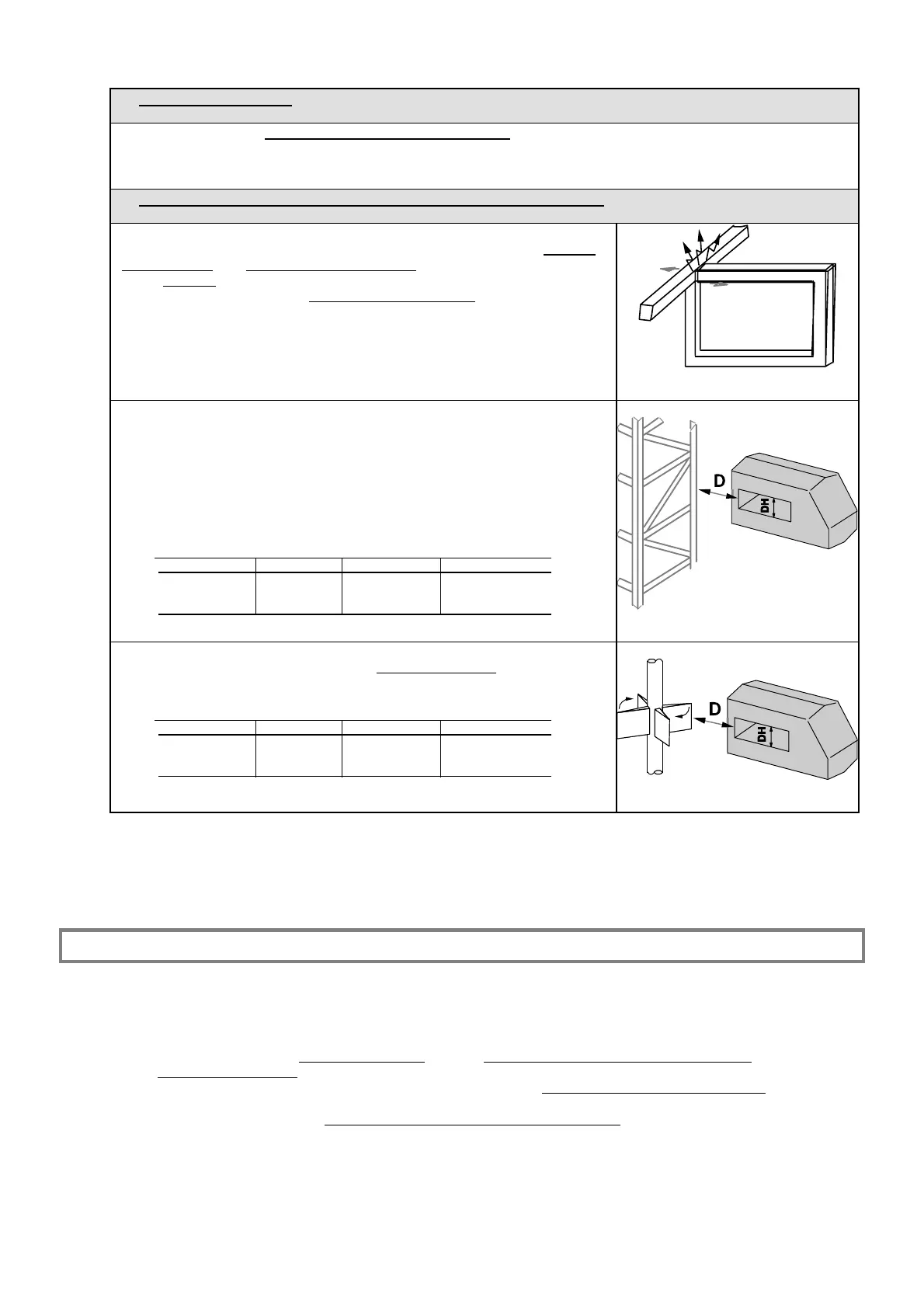
Moving metal structures
Such structures, especially when of a considerable mass
(mills, hoppers,
etc.), must be located as far away as possible from the probe.
| Model THS/M THS/A Other models |
| |
| D ≥ 10 DH ≥ 10 DH ≥ 6 DH |
| |
Fig. II-3 Moving metal structures
General guidelines for electrical installation
Possible sources of electrical interference may be power supply cables (electromagnetic fields generated by alternating
currents) or impulsive electromagnetic sources (electrical motors with high start-up absorption of power and their
power supply cables, fluorescent lights, emergency generators, remote control devices, etc.) located near the probe.
• Power supply cables to other devices. The route of the conductors must never be allowed to create a large-scale
electromagnetic loop. The power supply cables
must be distanced as far as possible from the probe and braided with
the shortest possible pitch. In general, it is advisable that the power supply cable harnesses be inserted into special
insulated channels. In the event that the conductors have to pass near the probe of the metal detector, it is advisable
that they be inserted into an iron tube, either electro-welded or drawn, which is at least 2 mm thick and has a suitable
diameter. N.B: this solution is only valid if the tube is not subject to vibrations
; should it be subject to vibrations this
solution could even be counter-productive.
• Grounding. This connection must lead directly to the electrical power supply board and must not be derived from any
other electrical devices.