THS – FI022GB2K8v3 --- V - MAINTENANCE
22
Non-integrated THS system supplied without conveyor belt: detailed
construction notes and selection of operating parameters
The following notes provide additional instructions necessary for installing the
detector on a conveyor belt or other transport system set up by the customer.
For the installation checks you need to be able to switch on the system, understand the signals given during use and set
the applicable operating parameters. These operations are described in the first part of the “USE” section.
Mechanical Installation
Controls
According to regulation EN60204-1, the main switch and the other controls to be used by the operator must be at a
height ranging from 600mm to 1,800mm from the flooring.
If it proves impossible to comply with this measurement due to the configuration of the system, an additional control unit
which complies with the regulations must be set up.
Mechanical installation of the metal detector
Mount and fix the probe onto the structure of the conveyor belt (use the four holes located on the base-plates. N.B.: on
some models the base-plates can be fixed in two different positions to adapt to the shape of the load-bearing structure).
The belt must pass through the tunnel.
The structure must be stable and not subject to vibrations.
Mechanical installation of the power supply unit
The power supply unit must be firmly attached to the load-bearing structure by means of four screws; it must be close to
the central electronics unit and to the external subsidiary devices connected to the unit (photocell, ejector, etc.).
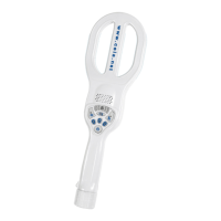
Mechanical installation of the THS/G probe
Mount the probe on the pipe carrying the material to be inspected and fix it with screws and plastic spacers, using the
holes provided on underside ( see Fig. "Dimensions of the probe", dimension FHW).
Fix the control unit in a convenient position for use, within the limit set by the length of the probe connecting cable.
Fix the cable which connects the probe to the power supply unit so that it can not oscillate or vibrate.
If the cable is too long, DO NOT CUT THE CABLE: COIL UP THE EXCESS!
Proximity limits around the THS/G probe
The distance between the probe and fixed or moving masses depends on the sensitivity selected and on the size of the
masses. The figure below shows:
• the minimum distance D between the probe S and the support plate P
• the minimum distance H between the probe S and the deflector f, based on a sensitivity setting of 280 and a flap-
type deflector in stainless steel. If the sensitivity or the type of deflector is changed, this minimum distance may
decrease: using the procedure for checking environmental interference (see “Maintenance” section), check that
activation of the deflector does not influence operation of the metal detector.