THS – FI022GB2K8v3 --- V - MAINTENANCE
52
It is strictly forbidden to start up the system if all safety features are not properly functional. Tampering with the safety
features is also forbidden, and voids all responsibility of the manufacturer for any damage caused.
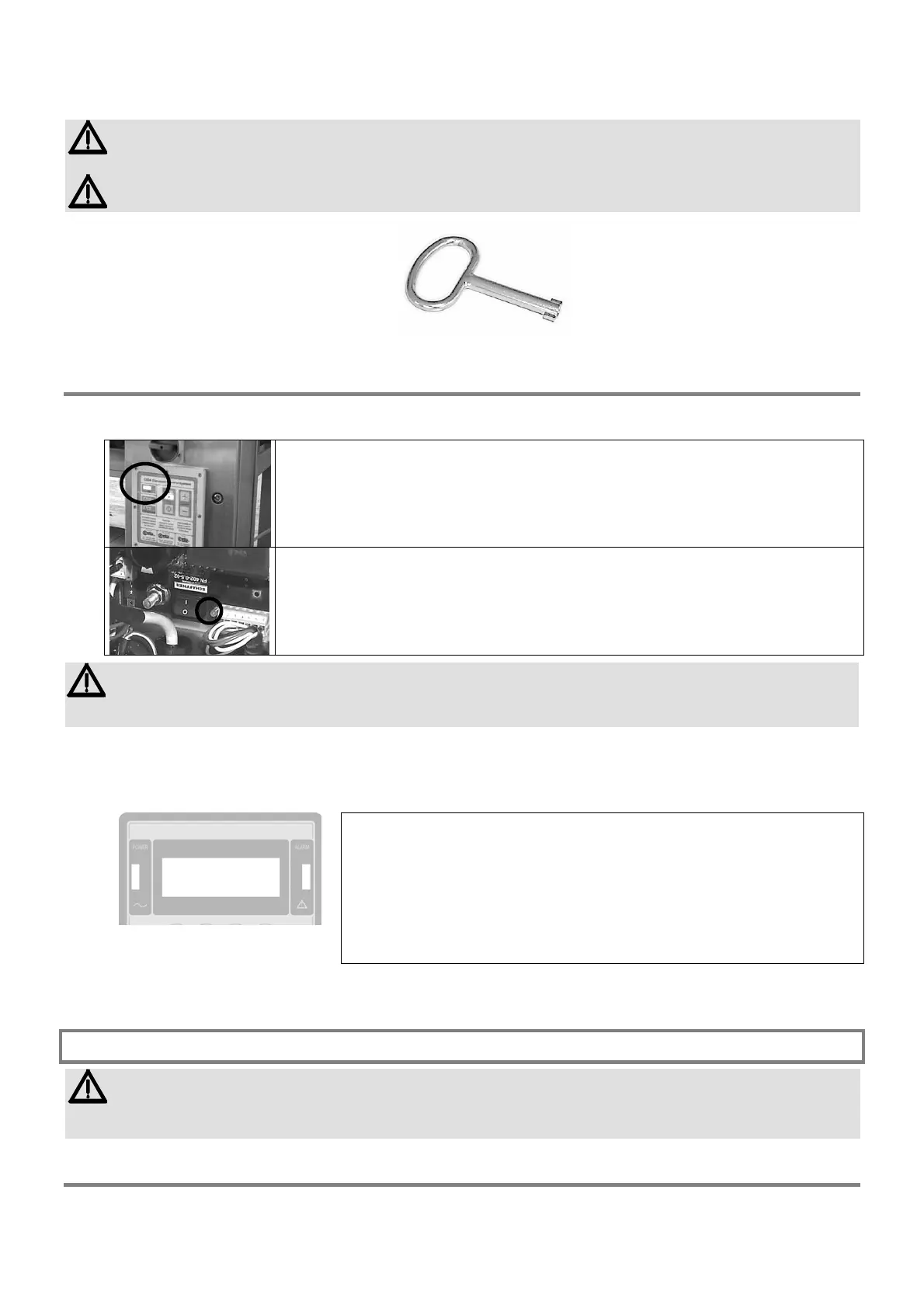
Keep the power supply unit panel closed. The key must always be in the possession of an authorised person.
Fig. III-6
Signals at power-up
The detector is designed to be switched on directly from the electrical panel that controls the production line.
The power supply unit does however contain an auxiliary switch I2, which is normally in the ON position.
The presence of mains power supply is signalled by the lighting up of the indicator located on
the control panel (Conveyor Control System) ...
Fig. III-7a
... or of the green LED L2 located on card ALM, near switch I2 (Control Power Box).
Fig. III-7b
When it is first powered up, the Metal Detector’s configuration includes 5 factory-set passwords (shown in the
test card at the end of the manual).
It is extremely important that the person in charge of the detector modifies the passwords in order to avoid
unauthorised access to programming.
When the device is turned on, the display lights up, as do the indicators located on the front of the
electronics unit.
More specifically, the display shows, in sequence, the serial number and the version of the software program that drives
the power supply unit; after that the following is displayed:
THS V3.xxx
Product productname
|
Fig.III-8
in which:
THS identifies the model
V3.xxx identifies the software version of the metal detector
productname indicates the type of programming, specific to one product,
which may be chosen from among 250 stored sets, of which
249 can be defined by the user (see Programming chapter);
each stored programming set is customised and relates to a
specific product to be monitored.
Signals given during use
On models where there is a control panel on both the probe and the power supply unit (because the probe is installed in
a position which is inaccessible to the operator), the electronics unit display is disabled (the message “Disabled”
appears).
Indication of the received signal
On the fourth line of the display the signal being received is displayed by means of a horizontal illuminating bar,
subdivided into 20 sections. When the signal increases, the bar extends towards the right. The alarm threshold
corresponds to 10 illuminated sections: the sections from 1 to 10 are bars, those from 11 to 20 are asterisks
I2
L2