THS – FI022GB2K8v3 --- V - MAINTENANCE
28
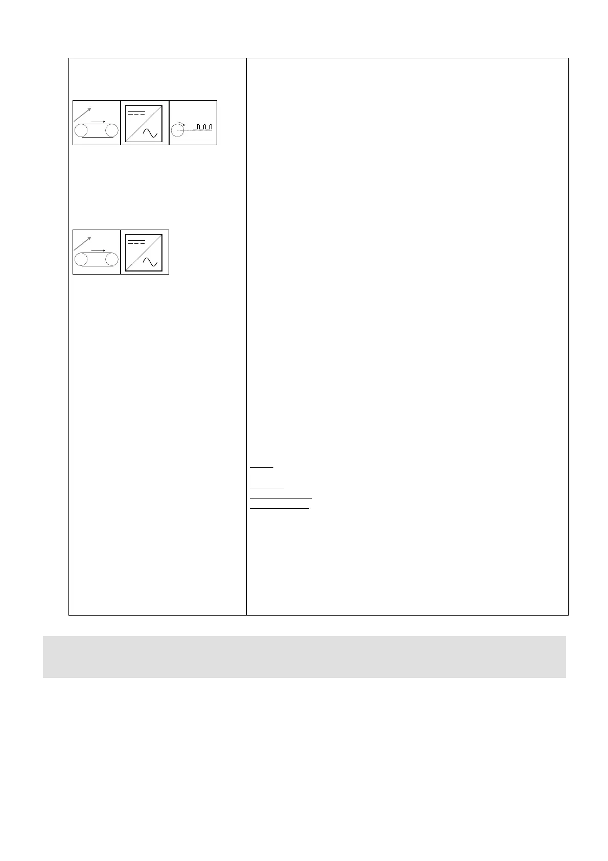
Variable-speed application
with inverter card, with
encoder
V
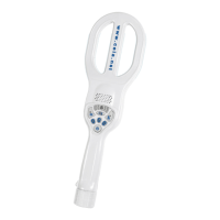
Variable-speed application
with inverter card, without
encoder
V
• BS should be assigned the desired value of the transit speed (the current
speed is detected by the system based on the working location of the
inverter, or via an encoder if fitted).
• Assign to the KE parameter the number of pulses per revolution of the
encoder.
• Assign to the DI parameter the value of the diameter of the motor roller
(see table)
• Assign the maximum motor operating frequency to parameter MI.
• Assign the maximum motor current consumption to parameter
CU.
Some structural relationships must be observed:
BL ≤ BS ≤ BM
BL ≥ 20 x KT
BM ≤ 60 x KT
The parameter KT depends on the system configuration, and can be
determined using the following procedure (it is necessary to obtain a transit
speed measurement device):
1. set KT=1.000
2. set BS=50
3. activate the motor and measure the speed of transit Vn
4. calculate KT = Vn/50
By changing the value of BS, the speed can vary between 40% and
(2 x
MI)%
of the nominal value of the motor (corresponding to operation at 50Hz).
N.B.: by modifying the value of KT, the parameters BL and BM are
automatically set to nominal values, respectively 20 x KT and
MI x KT.
BL and BM can also be modified manually.
Example:
Motor: operating frequency 50Hz ; maximum frequency 60Hz; maximum
current 3A;
Encoder 100 impulses/rev.;
Roller diameter 60mm, belt thickness 2mm;
Desired speed
45m/', minimum 25m/', maximum 50 m/'.
• Set: MI=60, CU=3.000, DI=60+(2x2)=64
• Determine KT via the procedure described above:
KT=1.000, BS=50 measured Vn =55 m/' KT=55/50=1.100
• Set BL=25 (correct value to give 20KT=22)
• Set BM=50 (correct value to give MI x KT=66)
• Set desired speed BS=45
N.B.: The BS parameter is memorised individually for each type of product defined. If
required, several speed parameters may be set for the same material by defining an
equal number of product types.