THS – FI022GB2K8v3 --- I - DESCRIPTION
2
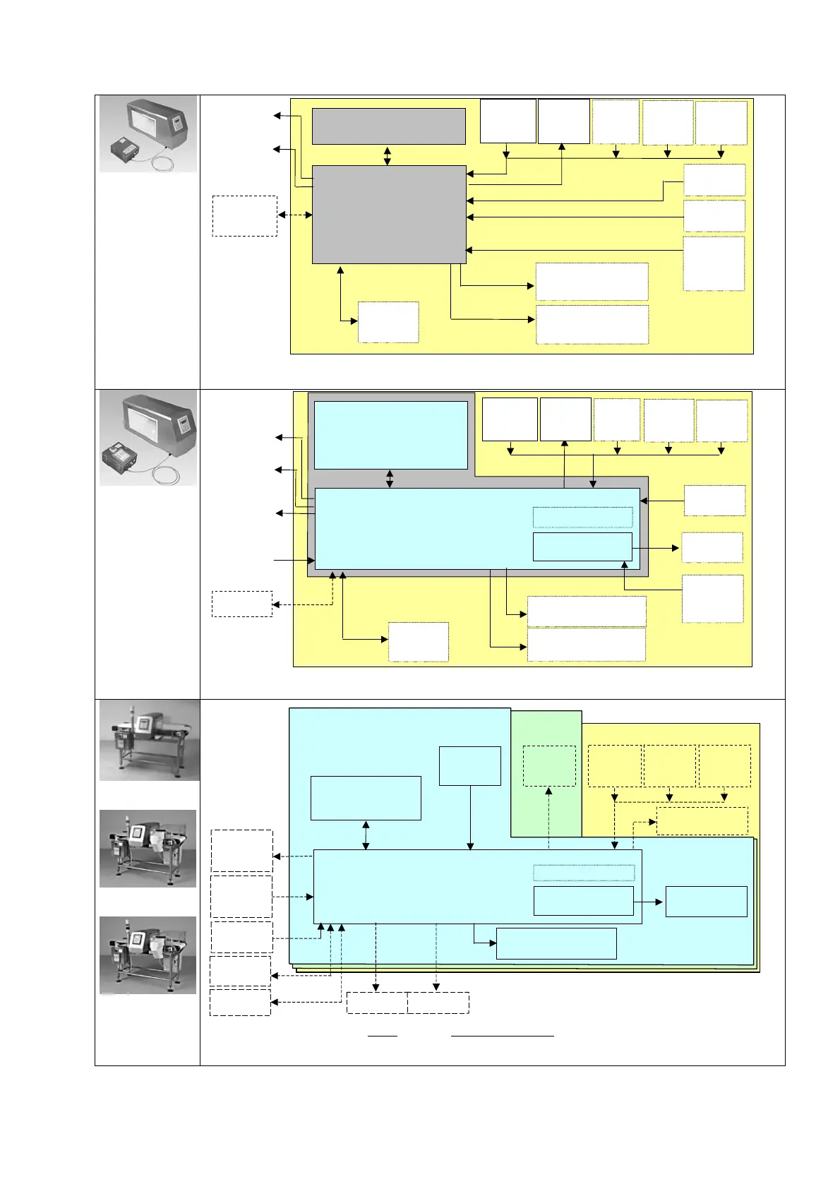
THS-Control
Power Box
Probe-Metal Detector
Power supply unit
(Control Power Box)
Product
transit
photocell
set-aside
full
sensor
ejection
confirm
sensor
Alarm reset
contact
Inhibition
contact
ejector
buzzer/flashing light
Computer
or printer
Encoder
to measure belt
movement
Flashing light
indicating test due
Air
pressure
sensor
Conveyor
Belt
malfunction
alarm
bar-code
reader
Fig I-2a - Block diagram of the system CEIA THS-Control Power Box system
THS-Conveyor
Control System
Probe-Metal Detector
Power supply unit
(Conveyor Control System)
downstrea
belt author-
isation
Encoder
to measure belt
movement
motor
upstream
belt
authorisation
Alarm reset
Inhibition
contact
malfunction
alarm
buzzer/flashing light
Motor driver card
Computer
or printer
bar-code
reader
Flashing light indicating
test due
Product
transit
photocell
set-aside
full
sensor
ejection
confirm
sensor
ejector
Air
pressure
sensor
Conveyor
Belt
Fig I-2b - Block diagram of the system CEIA THS-Conveyor Control System.
THS-FB/1
THS-FB/2
THS-FB/3
THS-FB/3
Probe-Metal
Detector
Power supply unit
(Conveyor Control System)
downstream
belt author-
isation
motor
upstream
belt
authorisation
Alarm reset
Inhibition
contact
malfunction alarm
buzzer/flashing light
MDL inverter card
Computer
or printer
bar-code
reader
Flashing light
indicating test due
Conveyor Belt
CEIA
THS-FB/2
THS-FB/1
Product
transit
hotocell
set-aside
full
sensor
ejection
confirm
sensor
ejector
Air
presssure
sensor
Fig I-2c - Block diagram of a CEIA
THS-FB integrated system including the conveyor belt, the THS
unit, the Conveyor Control System power supply unit and the sensors and actuators needed for
operation.