M-Series Operator’s Manual 4/9/15
10-62
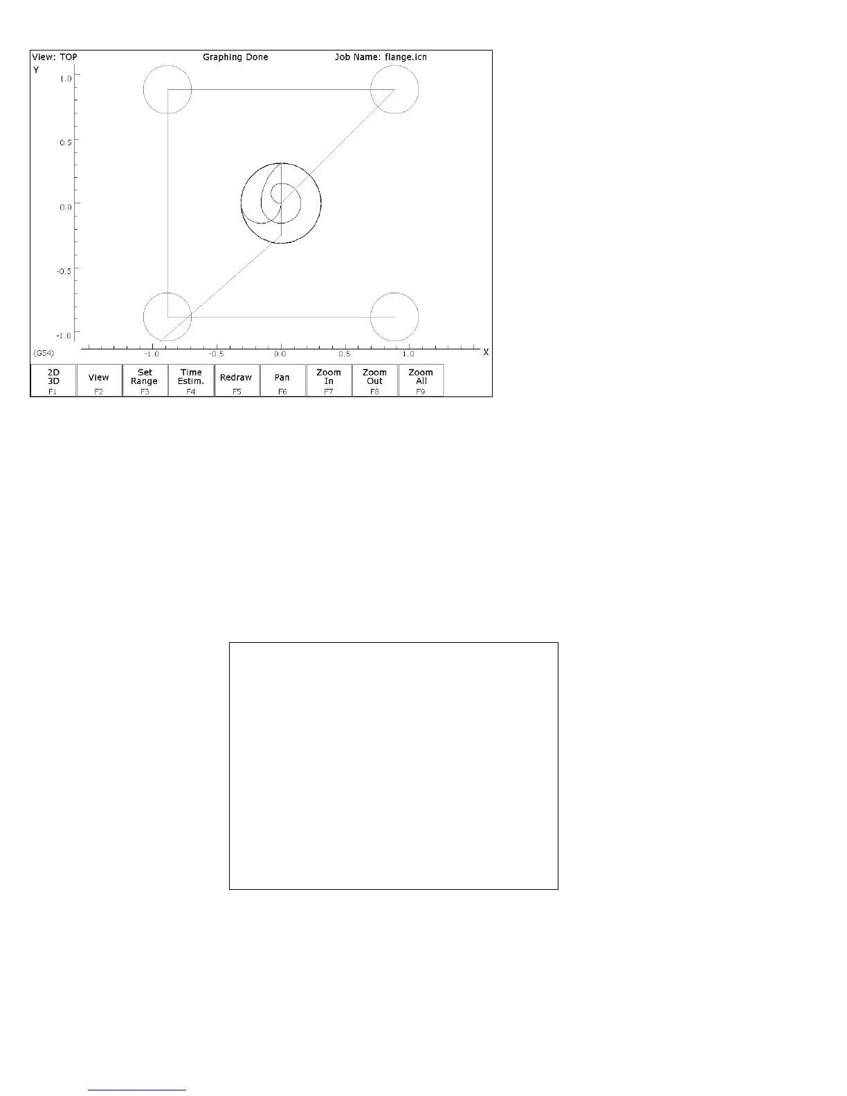
FIG. 2 - Graphics screen showing bolt holes and circular pocket
ESC/CANCEL Return to the editing screen.
F10 - Accept Keep selected values.
F5 -Cycles Access the list of available Canned Cycles.
F7 - Frame Now add an outside frame to cut the flange out of the material.
The flange is 3.0000 inches long by 3.0000 inches wide, and has
rounded corners with 0.2500-inch radii.
N0050 Frame mill
Frame :
Outside Rect
Center: X :
0.0000
Y :
0.0000
Surface Height
:
0.0000
Length X :
3.0000 INC
Width Y :
3.0000 INC
Corner Radius :
0.2500
Depth: Total
:
0.5000 INC
per Pass :
0.2500
Plunge Rate :
2.0000
Plunge Type :
Ramped
Plunge Angle :
0.00°
Cut Type :
Conventional
Feedrate :
10.0000
F8 - Graph Display a preview of the part up to this point. This preview can
be used to detect problems that may occur if the part was cut now.