M-Series Operator’s Manual 4/9/15
List of Rigid tapping setup parameters – see Chapter 14 for more details
Parameter
Function
34 Spindle Encoder Counts/Rev
35 Spindle Encoder Axis Number
36 Rigid Tapping Enable/Disable
37 Spindle Deceleration Time
68 Minimum Rigid Tapping Spindle Speed
69 Duration For Minimum Spindle Speed
74
M-Function executed at bottom of tapping cycle
84
M-Function executed at return to initial point of tapping cycle
82 Spindle Drift Adjustment
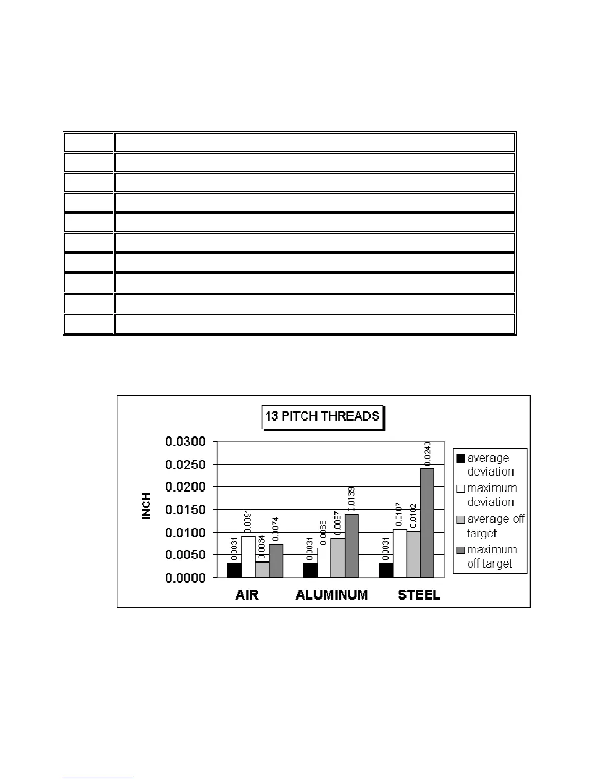
Graphic representation of test results for precision
The above charts show test results of rigid tapping, utilizing version 7.14 software. The tool used in the
testing was a ½-13 spiral fluted tap with TiN coating. Coolant used was water base soluble oil. Hole size was
.4218. Tapping depth was .800. Also note that the parameters were adjusted to cut air, and not changed for
aluminum or cold rolled steel for these tests. It can be seen, as the material changes, so does the off target
values. This is due in part to the amount of torque required from the spindle to cut the various types of
material. For testing purposes, the parameter settings for the above results were as follows.
Parameter 36 = 1, Parameter 37 = 3, Parameter 68 = 100, Parameter 69 = 1.25, Parameter 82 = 108