M-Series Operator’s Manual 4/9/15
Parameter 349, 352, and 355 – MPG/Handwheel Detents per Revolution 1, 2, and 3
This value is the number of clicks (detents) per revolution. It is the number of divisions or markings on the mpg or
handwheel. Moving the mpg or handwheel one detent or division will cause the motor to move one jog increment
(depending on the multiplier x1, x10, x100, etc). . Note: PLC program interaction is needed to enable an MPG or
handwheel.
Parameter 350, 353, and 356 –MPG/Handwheel Encoder Counts per Revolution 1, 2, and 3
This value is the number of counts generated per rotation of the mpg or handwheel. Note: PLC program interaction is
needed to enable an MPG or handwheel.
Parameters 357-364 – Axis Drive Max RPM for Axes 1-8
These parameters allow you to set the drive/motor max rate capability (in RPMs) for use by the PID algorithm for the
calculation of the axis KV1 contribution. This value is independent from the axis Max Rate setting in the Jog
Parameters menu, which is used by the control software. However, for those axes whose corresponding parameters are
set to 0 (the default) the the PID algorithm will use the axis Max Rate setting in the Jog Parameters for the calculation
of the axis KV1 contribution. These parameters are intended for 3
rd
party velocity mode drives that have a different
max rate setting than that of the control software.
Parameters 365 – Drive power-on delay
This specifies the number of milliseconds that the MPU11 will wait between the moment that drive power first comes
on and the start of commanded motion. However, this does not work for the case of turning off a single axis using
M93, moving a different axis, and then moving the powered off axis. The default value is 0 which means no delay.
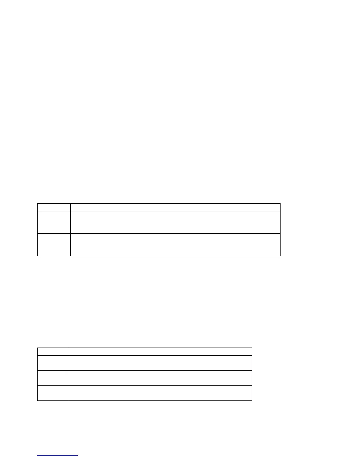
Parameters 366 / 367 – Probe / TT1 deceleration multiplier
Parameter
Function
366 Probe deceleration multiplier:
This factor adjusts the deceleration rate of probing moves coming to a stop due
to probe hit.
367 TT1 deceleration multiplier:
This factor adjusts the deceleration rate of TT1 tool measuring moves coming to
a stop due to tool touch detect.
The normal axis acceleration rate (configured by dividing the Max Rate in the Jog Parameters screen by the Accel
Time in the PID Config screen) is multiplied by the value of these parameters to determine the actual decelerations
used for each situation. A value higher than 1 will cause a more abrupt deceleration than the normal axis
configuration. A value below 1 will cause a gentler deceleration.
Parameters 374-379 – ACDC Drive Debug Log Settings
These parameters are used by support technicians and should be left at value 0.
Parameters 392-394 – DP-7 parameters
These are parameters specific to the DP-7 probe and are used only if parameter 155 = 2.
Parameter
Function
392 DP-7 Pullback Distance:
The distance the probe moves off of the surface after a probing move.
393 DP-7 Pullback Feedrate:
The feedrate for the pullback move.
394 DP-7 Measuring Feedrate:
The feedrate for the slow measuring move.
Parameters 395 – Probing Setup Traverse Speed
This sets the probing traverse feedrate for the macro-based probing cycles on engine block systems.