GR740-UM-DS, Nov 2017, Version 1.7 444 www.cobham.com/gaisler
GR740
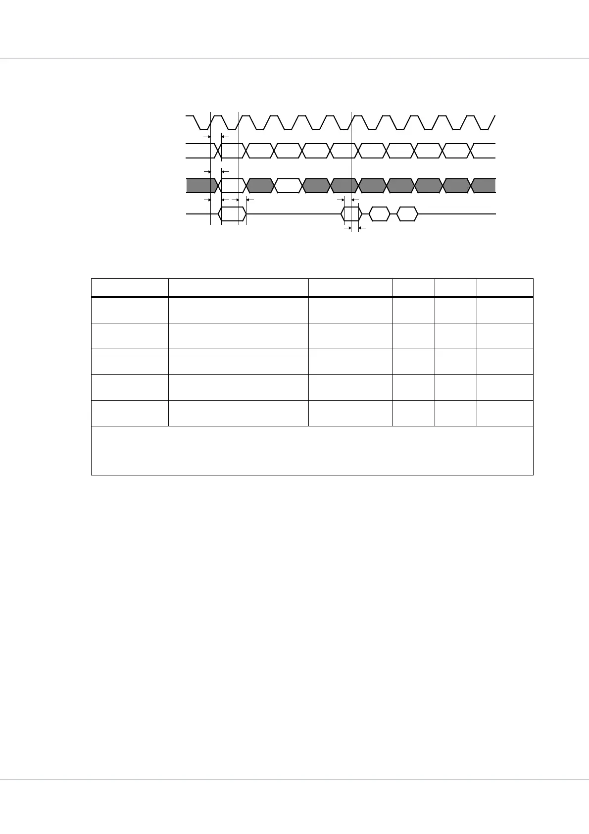
39.5.5 64-bit PC100 SDRAM Controller with Reeed-Solomon EDAC timing
The timing waveforms and timing parameters are shown in figure 58 and are defined in table 582.
Table 582.Timing parameters - SDRAM accesses
Name Parameter Reference edge Min Max Unit
t
SDRAM0
clock to output delay rising mem_clk_in
edge
3.12
13.3 ns
t
SDRAM1
clock to data output delay rising mem_clk_in
edge
3.12
13.3 ns
t
SDRAM2
data clock to data tri-state delay rising mem_clk_in
edge
0
1)
30.0
2)
ns
t
SDRAM3
data input to clock setup rising mem_clk_in
edge
2.76 - ns
t
SDRAM4
data input from clock hold rising mem_clk_in
edge
2.1 - ns
Notes:
1)
This parameter is guaranteed by design and is not tested
2)
This parameter is determined by characterization and is not tested
Figure 58. Timing waveforms - SDRAM accesses
mem_casn, mem_rasn
mem_clk_in
mem_wen, mem_sn[]
mem_dqm[]
write nop read nop nop term nop nop nop
mem_addr[]
mem_dq[]
t
SDRAM3
t
SDRAM0
t
SDRAM0
t
SDRAM2
t
SDRAM1
t
SDRAM4