GR740-UM-DS, Nov 2017, Version 1.7 448 www.cobham.com/gaisler
GR740
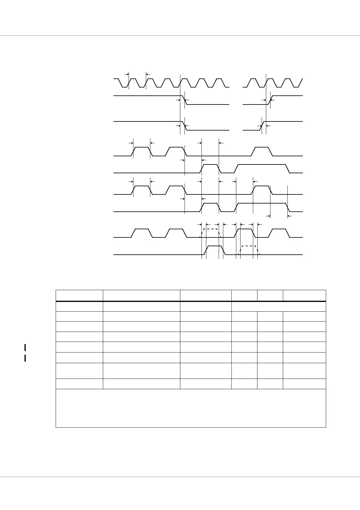
39.5.10 SpaceWire router interface timing
The specifies the timing for the Spacewire router links that are interfaced via LVDS signals. The tim-
ing waveforms are shown in figure 63. Timing parameters are defined in table 587.
Table 587.Timing parameters
Name Parameter Reference edge Min Max Unit
t
SPW0
transmit clock period - see Table 579
t
SPW1
clock to output delay - - - not applicable
t
SPW2
input to clock hold - - - not applicable
t
SPW3
input to clock setup - - - not applicable
t
SPW4
output data bit period -
2.5
2)
-ns
t
SPW5
input data bit period -
2.5
2)
-ns
t
SPW6
data & strobe input edge separa-
tion
-
2.0
2) 3)
-ns
t
SPW7
data & strobe output skew - -0.4
0.4
3)
ns
1)
Internal SpaceWire clock generated from PLL or from spw_clkin.
2)
Assuming SpaceWire PLL used in nominal configuration
3)
Edge separation and skew limits refer to each pair of data/strobe signals separately. Global skew and separation over the
entire set of eight pairs is not specified.
Figure 63. Timing waveforms
t
SPW1
spw_txd, spw_txdn
internal spw_clk
t
SPW1
t
SPW2
spw_rxd, spw_rxdn t
SPW3
spw_txs, spw_txsn
spw_rxs, spw_rxsn
t
SPW0
spw_txd, spw_txdn
spw_txs, spw_txsn
t
SPW4
t
SPW4
t
SPW4
spw_rxd, spw_rxdn
spw_rxs, spw_rxsn
t
SPW5
t
SPW5
t
SPW5
spw_txd, spw_txdn
spw_txs, spw_txsn
t
SPW7
t
SPW6
t
SPW6