Engineer Menu 1-4 Engineering Manual
40
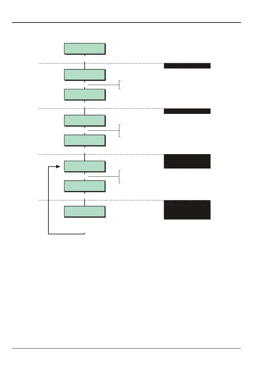
Flowchart for custom outputs:
Outputs 6
Custom Outputs
Custom Output 1
e.g.
[
Eng 1 Menu 4
Outputs
Custom Output 2
Custom 2-1 (OR)
Always Off
Custom 2-2 (OR)
Always Off
Outputs 1
Panel
[
|
[
[
6
|
e.g.
X
To select custom output:
Press or
"
"
|¬
to scroll, or
Press the custom output number (e.g. 1)
To select the gate:
Press or
"
"
|¬
to scroll, or
Enter the gate number (1to 8)
Output Type 1
System
Follow from Step 3 in the
flowchart shown in the
previous section
Press or custom outputs. See
previous section for other output types
6
f
1. SELECT OUTPUT TYPE
2. SELECT OUTPUT NUMBER
3. SELECT WHICH OF EIGHT
GATES OF THE CUSTOM
OUTPUT TO PROGRAM
4. SELECT WHETHER GATE
FOLLOWS SYSTEM, WARD,
ZONE, USER CODE OR
OUTPUT GROUP
If you are using outputs from the control panel or its network devices, you need to use the
Outputs option to specify the event that should cause the output to activate. For example, if
you select the Fire Alarm event for an output, the output will activate when a Fire zone triggers.
Step 1 – Select Output Type
Select the type of output you want to set up:
1 – Panel
Select this option to set up output 1, 2, 3, 4 or 5 on the control panel PCB. Outputs 1 and
2 are relays (voltage-free contacts); outputs 3, 4 and 5 are transistor outputs.
Please refer to the control panel's Installation Instructions for details of how these outputs
operate and their electrical characteristics.
2 – Digi H/Wired
Select this option to set up any of the digital communicator outputs on the control panel
PCB.