FC 300 Design Guide
How to Install
Theelectronicthermalrelay(ETR)oftheadjustablefrequencydrivecannotbeusedasmotorprotectionfor
an individual motor in system s with parallel-connected motors. Provide further motor protection by, e .g.,
thermistors in each motor or individual thermal relays. (Circuit breakers are not suitab le as protection).
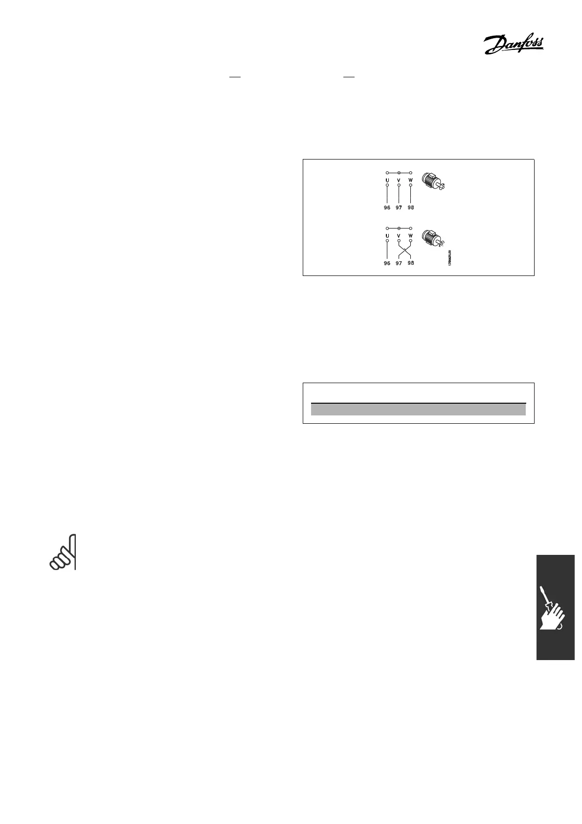
" Direction of Motor Rotation
The default setting i s clockwise rotation
with the adjustable frequency drive output
connected as follows.
Te rminal 9 6 connected to U-phase
Terminal 97 connected to V-phase
Terminal 98 connected to W-phase
The direction of motor rotation is changed by
switching two motor phases.
" Installation of Brake Cable
(Only for adjustable frequency drives ordered with brake chopper option).
The connection cable to the brake resistor must be shie lded.
1. Connect the shield by means of cable
clampstotheconductivebackplateonthe
adjustable frequency drive and to the metal
cabinet of the brake resisto r.
2. Size the brake cable cross-section t o
match the brake torque.
No. Function
81, 82 Brake resistor terminals
See Brake instructions, M
I.90.FX.YY and MI.50.SX.YY for more information about safe installation.
NOTE
Voltages up to 960 V DC, dep end ing on the supply voltage, may occur on the terminals.
117
MG.33.B6.22 - VLT is a registered Danfoss trademark

 Loading...


