EasyManuals Logo

Danfoss FC 300 Design Guide

Danfoss FC 300
309 pages
To Next Page IconTo Next Page
To Previous Page IconTo Previous Page
Page #105 background imageLoading...
Page #105 background image
FC 300 Design Guide
How to Install
" Access to Control Terminals
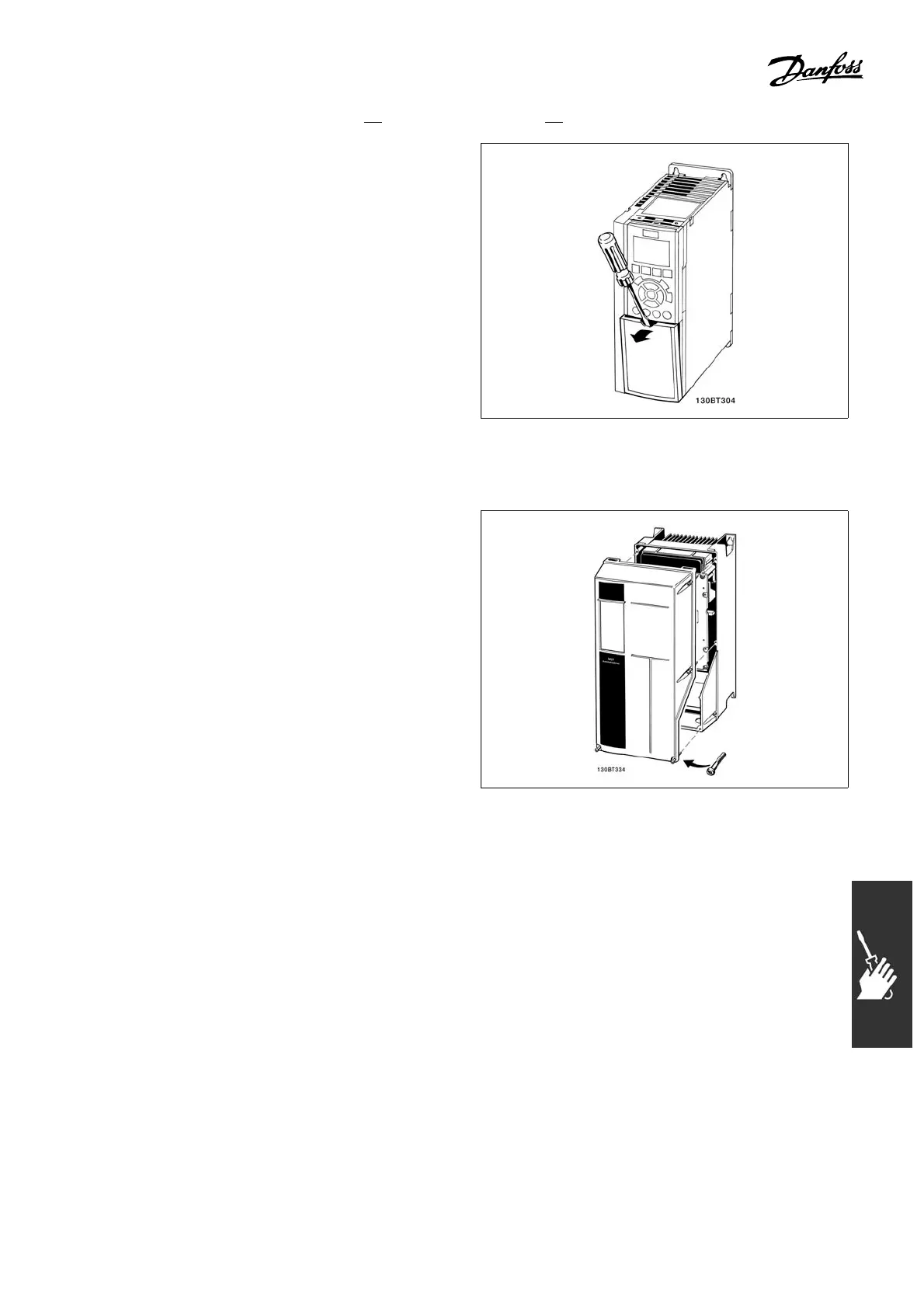
All terminals to the control cables are located
underneath the terminal cover on t he front of the
adjustable frequency drive. Remove the terminal
cover by means of a screwdriver (see illustration).
A1, A2 and A3 enclosures
A5, B1 and B2 en closures
"
Control Terminals (FC 301)
Drawing refere nce numbers:
1. 8-pole plug, digital I/O.
2. 3-pole plug, RS 485 b
us.
3. 6-pole, analog I/O.
4. USB Connection.
Control Terminals (
FC 302)
Drawing refere n ce n
umbers:
1. 10-pole plug, digi
tal I/O.
2. 3-pole plug, RS 485 bus.
3. 6-pole, analog I/O.
4. USB Connection.
105
MG.33.B6.22 - VLT is a registered Danfoss trademark

Table of Contents

Other manuals for Danfoss FC 300

Questions and Answers:

Question and Answer IconNeed help?

Do you have a question about the Danfoss FC 300 and is the answer not in the manual?

Danfoss FC 300 Specifications

General IconGeneral
EnclosureIP20
ApprovalscUL, UL, CE
EMC filterBuilt-in
Communication OptionsCANopen, PROFIBUS DP
Protection FeaturesOvercurrent, Overvoltage, Undervoltage, Overtemperature, Short Circuit
Output Voltage0-100% of supply voltage

Related product manuals