FC 300 Design Guide
How to Install
" Mains Supply Interference/Harmonics
An adjustable frequency drive takes up a
non-sinusoidal current from mains, which increases
the input current I
RMS
. A non-sinusoidal current
is transformed by m eans of a Fourier analysis
and split up into sine wave currents with different
frequencies, i.e. different harmonic currents I
N
with 50 Hz as the basic frequency:
Harmonic currents I
1
I
5
I
7
Hz 50 Hz 250 Hz 350 Hz
The harmonics do not affect the power consumption
directly but increase the heat losses in the
installation (transformer, cables). Consequently,
in plants with a high percentage of rectifie r
load, m aintain harmonic c urrents at a low
level to avoid overload of the transformer and
high temperature in the cables.
NOTE
Some of the harmonic currents migh
t d isturb communication equipment connected to the same
transformerorcauseresonanceinconnectionwithpower-factorcorrectionbatteries.
Harmonic currents compared to the RMS
input current:
Input current
I
RMS
1.0
I
1
0.9
I
5
0.4
I
7
0.2
I
11-49
<0.1
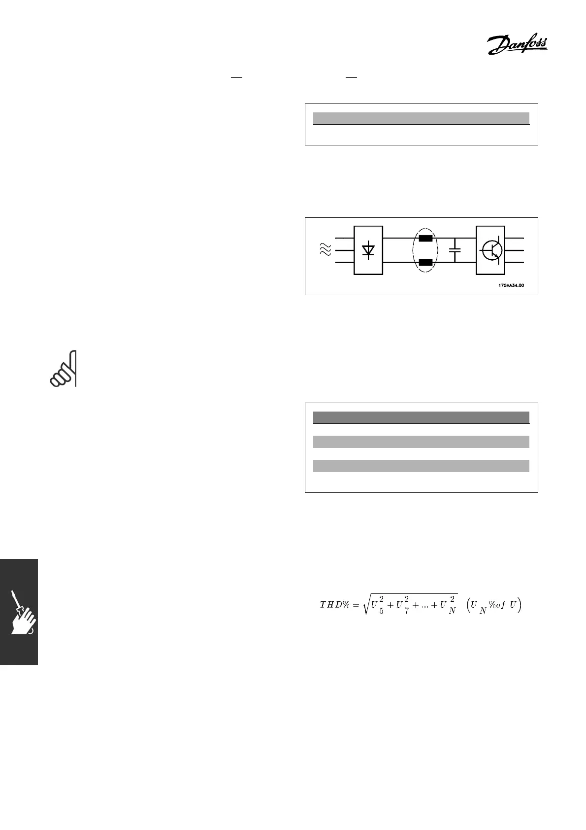
To ensure low harmonic currents, the adjustable frequency drive is equipped with intermediate circuit
coils as standard. This norm a lly reduces the inp ut current I
RMS
by 40%.
The voltage distortion on the mains supply depends
on the size of the harmonic currents multiplied
by the m ains impedance for the frequency in
question. The total voltage distort ion THD is
calculated on the basis of the individual voltage
harmonics using this formula:
124
MG.33.B6.22 - VLT is a registered Danfoss trademark