FC 300 Design Guide
Introduction to FC 300
" Speed PID Control
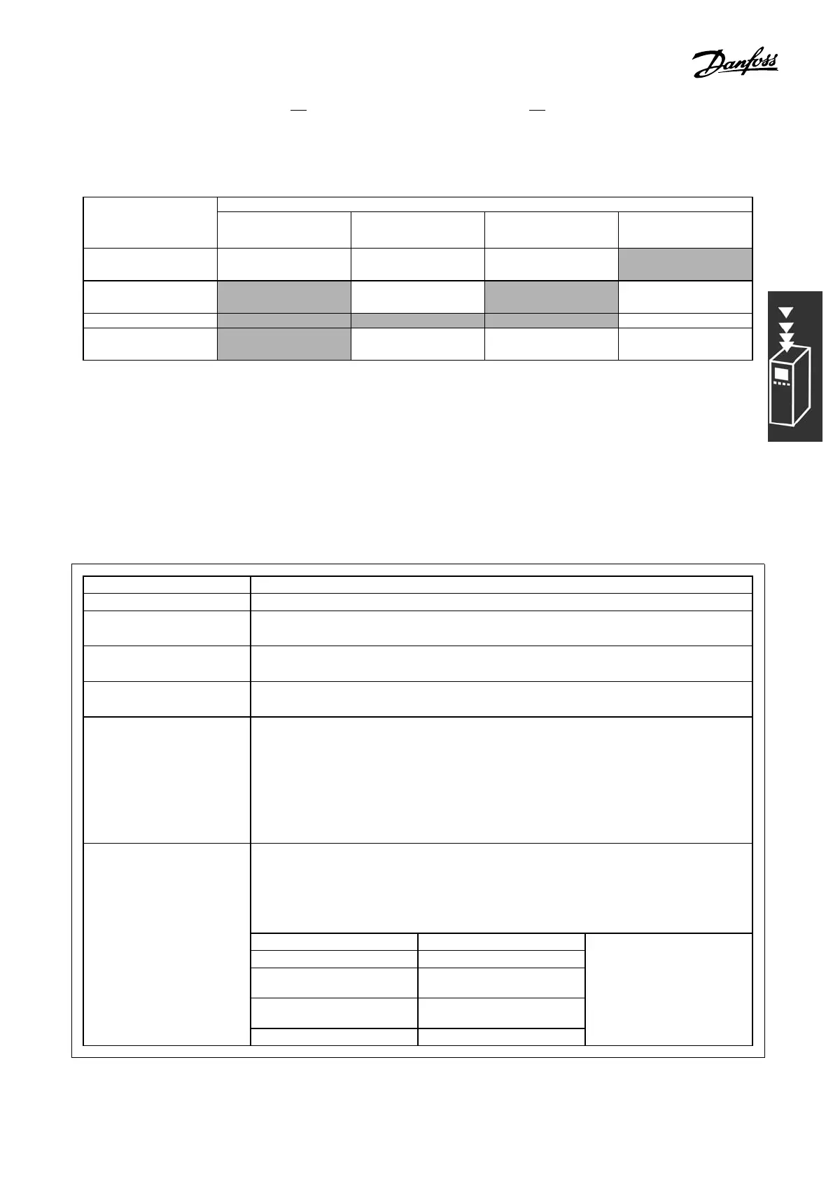
The table shows the control configurations where the Speed Control is a ctive.
Par. 1-01 Motor Control PrinciplePar. 1-00
Configuration
Mode
U/f VVCplus Flux sens orless Flux w motor feedb
[0] Speed open
loop
Not Active Not Active ACTIVE N.A.
[1] Speed
closed-loop
N.A. ACTIVE N.A. ACTIVE
[2] Torque N.A. N.A. N.A. Not Active
[3] Process
open-loop
Not Active ACTIVE ACTIVE
Note: "N.A." mea ns that the specific mode is not available at all. "Not Active" means that the
specific mode is available but the Speed Control is not active in that mode.
Note: The Speed Control PID will work under the default parameter setting, but tuning the p arameters
is highly recommended to optimize the motor control performance. The two Flux motor control
principles are specially dependent on proper tuning to yield their full potential.
The following parameters a re re levant for the Speed Control:
Parameter Description of function
Feedback Par. 7-00 Select from which input the Speed PID should get its feedback.
Speed PID Proportional
Gain Par. 7-02
The hig her the value, the quicker the control. However, too high a value
may lead to oscillations.
Speed PID Integral Time
Par. 7-03
Eliminates steady state speed error. Lower value means quick reaction.
However, too low a value may lead to oscillations.
Speed PID D iffe r entia-
tion Ti me Par. 7-04
Provides a gain proportional to the rate of change of the feedback. A setting
of zero disables the differ entiator.
Speed PID D iff. Gain
Limit Par. 7-05
If there are quick changes in reference or feedback in a given application -
which means tha t the error changes swiftly - the differentiator may soon
become too dominant. This is because it reacts to changes in the error.
The quicker the error changes, the stronger the differentiator gain is. The
differentiator gain can thus be limited to allow setting of the re asonabl e
differentiation time for slow changes and a suitably quick gain for quick
changes.
A low-pass filter that dampens oscillations on the feedback signal and
improves steady state performa n ce. However, too large a filter time will
deteriorate the dynamic performance of the Speed PID control.
Practical settings of Par 7-0 6 taken from the number of pulses per revolution
on from encoder (PPR):
Encoder PPR Par. 7-06
512 10 ms
1024 5ms
2048 2ms
Speed PID Lowp ass
Filter T ime Par. 7-06
4096 1ms
31
MG.33.B6.22 - VLT is a registered Danfoss trademark