FC 300 Design Guide
How to Program
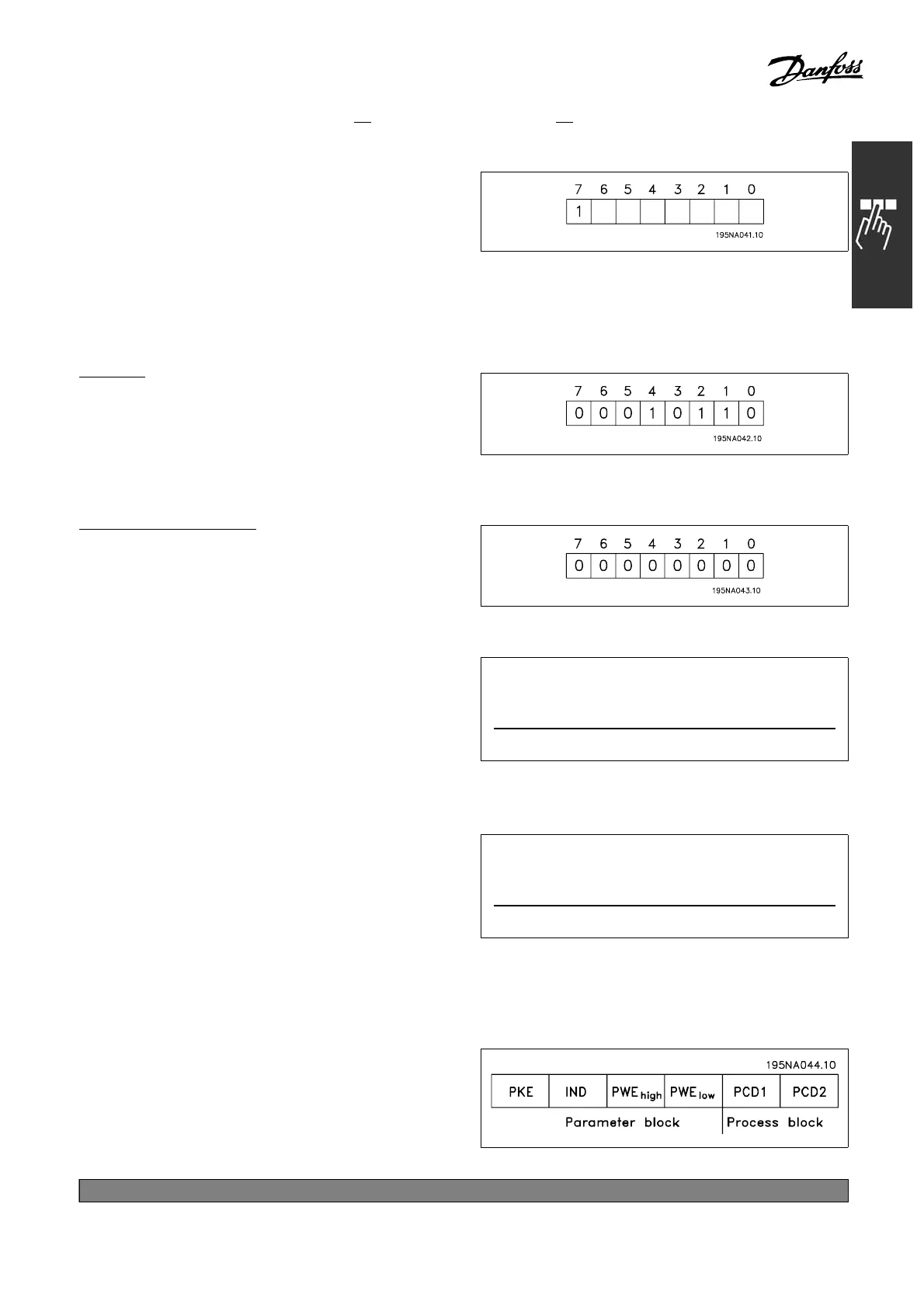
2. Address format 1-126
The byte for address range 1 - 126 has
the shown profile:
Bit 7 = 1 (address format 1-12 6 active)
Bit 0-6 = Adjustable f re quency drive address 1-126
Bit 0-6 = 0 Broadcast
The slave returns the address byte unchanged to
the master in the response telegram.
E
xample:
Writing to adjustable frequency drive address
22 (16H) with address format 1-3
1:
Data control byte (BCC)
The data control byte is explained in this example:
Before the first byte in the telegram is received,
the Calculated Che ckSum (BCS) is 0 .
When the first byte (02H) is received :
BCS = BCC EXOR "first byte"
(EXOR = exclusive-or)
Each subsequent byte gates with BCS EXOR
and produces a new BCC, e.g.:
BCS =00000000(00H)
EXOR
1. byte =00000010(02H)
BCC =00000010(02H)
BCS =00000010(02H)
EXOR
2ndbyte =11010110(D6H)
BCC =11010100(D4H)
" Data Character (byte)
The structure of data blocks depends on the type of telegram. There are three telegram types,
and the type applies for both control telegrams (master=>slave) and response telegrams
(slave=>master). T he three types of telegram are:
Parameterblock: Usedtotransferparameters
between master and slave. The data block
is made up of 12 bytes (6 words) a nd also
contains the proce ss block.
*
default setting ()display text []value for use in communication via serial communication port
271
MG.33.B
6.22 - V LT is a registered Danfoss trademark