FC 300 Design Guide
Introduction to FC 300
" Control Structure in VVC
plus
Control structure in VVC
plus
open-loop and closed-loop configurations:
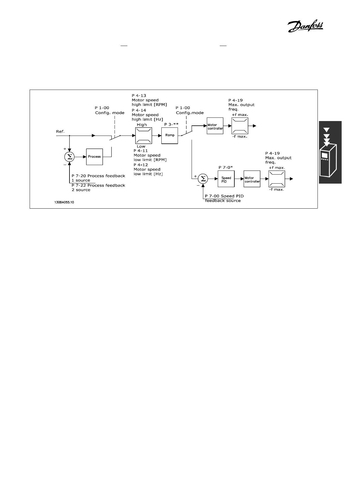
In the configuration shown in the illustration above, par. 1-01 Motor Control Princip le is set to “VVC
plus
[1]” and par. 1-00 is set to “Speed open-loop [0]”. The resulting refe rence from the refe rence handling
system is received and fed through the ramp limitation and speed limit ation before being sent to the motor
control. The output of the motor control is then lim ited by the maximum frequency limit.
If par. 1-00 is set to “Speed closed-loop [1]” the resul ting refere nce w ill be passed from the ramp limitation and
speed limitation into a speed PID control. The speed PID control parameters are located in the par. group 7 -0*.
The resulting reference from the speed PID control is sent to the m otor control lim ited by the frequency limit.
Select “Process [3]” in par. 1-00 to use the process PID control for closed-loop control of, e.g., speed or
pressure in the controlled application. The process P ID parameters are located in par. g roup 7-2* and 7-3*.
19
MG.33.B6.22 - VLT is a registered Danfoss trademark