FC 300 Design Guide
How to Install
" RS 485 Bus Connection
One or more adjustable frequency drives can be
connected to a control (or master) using the RS485
standardized interface. Terminal 68 is connected
to the P signal (TX+, RX+), while terminal 69 is
connected to the N signal (TX-, RX-).
Ifmorethanoneadjustablefrequencydriveis
connected to a m aster, use parallel connections.
In order to avoid potential equalizing currents in the shield, ground the cable shield via
terminal 61, which is connecte d to the frame via an RC link.
Bus termination
TheRS485busmustbeterminatedbyaresistor network at both ends. For this p urpose,
set switch S801 on the control card to "ON".
For more information, see the paragraph SwitchesS201,S202,andS801.
NOTE
Communication protocol must be set to FC MC p ar. 8-30.
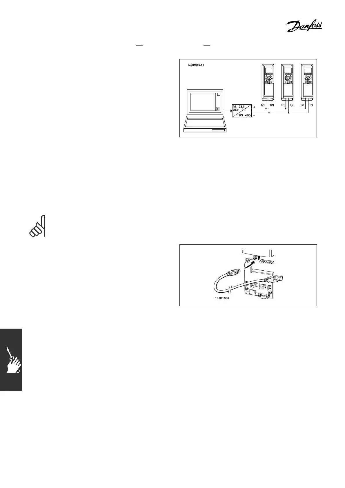
" HowtoConnectaPCtotheFC300
To control the a djustable frequency drive from a
PC, install the M CT 10 Setup Software.
The PC is connected via a standa rd (host/device)
USB cable, or via the R S -485 interface as
showninthesectionBus Connection in the
chapter How to P rogram.
USB connection.
118
MG.33.B6.22 - VLT is a registered Danfoss trademark

 Loading...


