FC 300 Design Guide
Introduction to FC 300
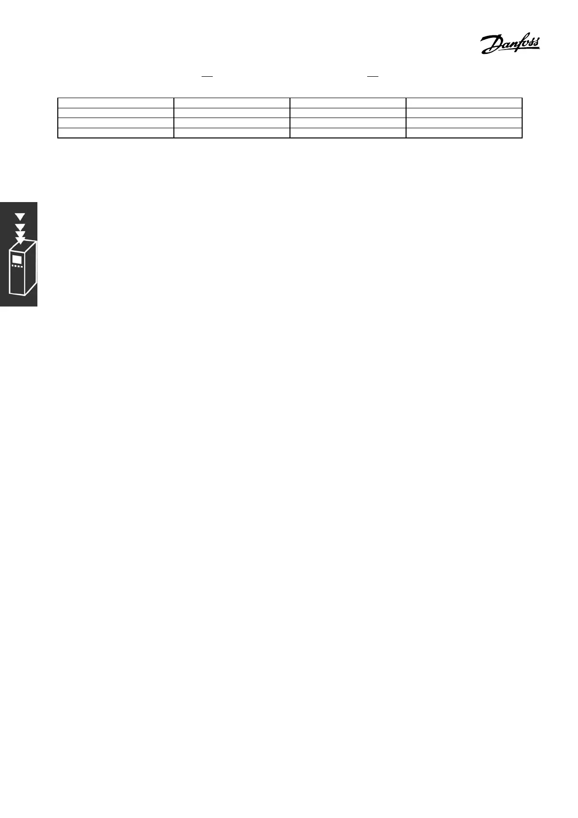
Type of Control Proportional Gain Integral Time Differentiation Time
PI-control 0.45 * K
u
0.833 * P
u
-
PID tight control 0.6 * K
u
0.5 * P
u
0.125 * P
u
PID some overshoot 0.33 * K
u
0.5 * P
u
0.33 * P
u
Table 1: Zi egler Nichols tuning for regulator, base
d on a stability bounda ry.
Experience has shown that the control setting according to the Ziegler Nichols rule provides
a g ood closed-loop response for many systems. The process o perator can perform final
tuning of the control iteratively to yield satisfactory control.
Step-by-step:
Step 1: Select only Proportional Control, meaning that the Integral time is selected to the
maximum value, while the differentiation time is selected to zero.
Step 2: Increase the value of the proportional gain until the point of inst ability is rea ched
(sustained oscillations) and the critical value of gain, K
u
, is reached.
Step 3: Measure the period of oscillation to obtain the critical time constant, P
u
.
Step 4: Use the table above to calculate the necessary PID control parameters.
" General Aspects of EMC Emissions
Electrical interfere nce is usually conducted at frequenci es in the range 150 kHz to 30
MHz. Airborne interference from the drive system in the range 30 MHz to 1 GHz is
generated from the inverter, motor cable, and the motor.
As shown in the illustration b elow, capacitive curre nts in the motor cable coupled with a high
dV/dt from the motor voltage generate leakage currents.
The use of a shielded motor cable increases the leakage current (see illustration below) because shielded
cables have higher capacitance to ground than non-shielded cables. If the leaka ge current is not f iltered,
it will cause gre ater interference on the mains in the radio frequency range below approx. 5 MHz. Sinc e
the le akage current (I
1
) is carried back to the unit through the shield (I
3
), there will in p rinciple only be a
small electromagnetic field (I
4
) from the shielded mo tor cable according to the below figure.
The shield reduces the radiated interference b ut increases the low-frequency interference on the
mains. The motor cable shield must be connected to the adjustab le frequency dr ive enclosure
as well as on the motor enclosure. This is best done by using integrated shield clamps so as to
avoid twisted shield ends (pigtails). These increase the shield impedance at higher frequencies,
which reduces the shield effect and increases the leakage current (I
4
).
If a shielded cable is us ed for Profibus, standard bus, relay, control cable, signal interface, and
brake, the shield must be mounted on the enclosure at both ends. In some situations, however,
it w ill be necessary to break the shield to avoid current loops.
40
MG.33.B6.22 - VLT is a registered Danfoss trademark