FC 300 Design Guide
How to Install
" Electrical Installation
NOTE
Cables General
Always comply with national and local regulations on cable cross-sections.
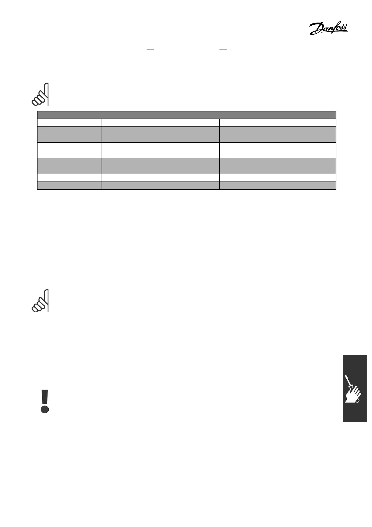
Tightening-up Torque
AFD size Cable for: Tightening-up torque
0.34-10 HP [0.25-7.5
kW]
Line, brake resistor, load sharing motor
cable
0.5-0.6 Nm
1.8 Nm
14.75-10 HP [11-15
kW]
Line, brake resistor, load sharing motor
cable
1.8 Nm
14.75-10 HP [11-15
kW]
Motor cable 1.8 Nm
Relay 0.5-0.6 Nm
Ground 2-3 Nm
" RemovalofKnockoutsforExtraCables
1. Remove the cable entry from the adjustable frequency drive (avoid foreign parts entering
the adjustable frequency drive when removing knockouts).
2. The cable entry must be supported around the knockout you intend to remove.
3. The knockout can now be removed with a strong mandrel and a hamm er.
4. Remove burrs from the hole.
5. Mount cable entry on adjustable frequency drive.
" Connection to Line Supply and Grounding
NOTE
The plug connec tor for power can
be removed.
1. Make sure the FC 300 is properly grounded.
Connect to ground connection (terminal 95).
Use screw from the accessor y bag.
2. Place plug connector 91, 92, 93 from the
accessory bag onto the terminals labele d
MAINS at the bottom of the FC 300.
3. Connect line wires to the line plug connector.
The ground conne ction cable cross-section
must be at least 3 .9 in
2
[10 mm
2
]or
have 2 rated line supp ly wires terminated
separately according to EN 50178.
The line supply connection is fitted to the line
supply switch if this is included.
97
MG.33.B6.22 - VLT is a registered Danfoss trademark