EasyManuals Logo

Danfoss FC 300 Design Guide

Danfoss FC 300
309 pages
To Next Page IconTo Next Page
To Previous Page IconTo Previous Page
Page #127 background imageLoading...
Page #127 background image
FC 300 Design Guide
Application Examples
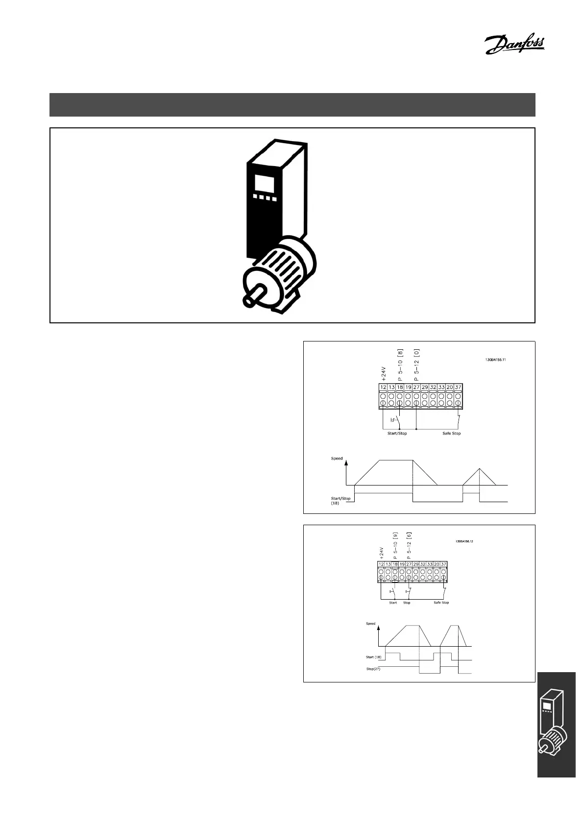
" Start/Stop
Terminal 18 = start/stop par. 5-10 [8] Start
Terminal 27 = No operation par. 5-12 [0] No
operation (Default coast inverse
Terminal 37 = S afe stop (FC 302 only)
Par. 5-10 Digital Input = Start (d efault)
Par. 5-12 Digital Input = coast inverse (default)
" Pulse start/stop
Te rminal 18 = start stop/ par. 5-10 [9] Latched start
Terminal 27= Stop par. 5-12 [6] Stop inverse
Terminal 37 = S afe stop (FC 302 only)
Par. 5 Digital input = Latched start
Par. 5 Digital input = Stop inverse
127
MG.33.B6.22 - VLT is a registered Danfoss trademark

Table of Contents

Other manuals for Danfoss FC 300

Questions and Answers:

Question and Answer IconNeed help?

Do you have a question about the Danfoss FC 300 and is the answer not in the manual?

Danfoss FC 300 Specifications

General IconGeneral
EnclosureIP20
ApprovalscUL, UL, CE
EMC filterBuilt-in
Communication OptionsCANopen, PROFIBUS DP
Protection FeaturesOvercurrent, Overvoltage, Undervoltage, Overtemperature, Short Circuit
Output Voltage0-100% of supply voltage

Related product manuals