FC 300 Design Guide
How to Install
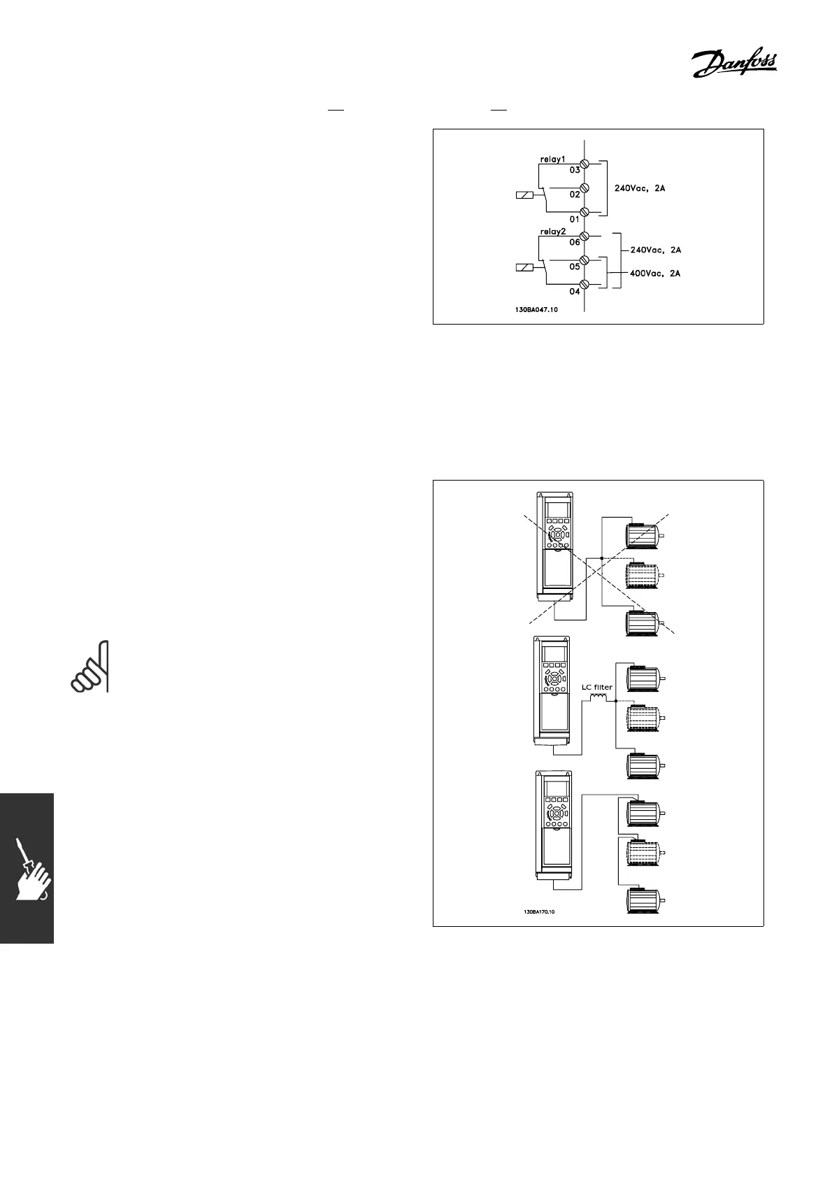
" Relay Output
Relay 1
• Terminal 01: common
• Terminal 02: normal open 240 V AC
• Terminal 03: normal closed 240 V AC
Relay 2 (F C 302 only)
• Terminal 04: common
• Terminal 05: normal open 400 V AC
• Terminal 06: normal closed 240 V AC
Relay 1 and relay 2 are programmed in par.
5-40, 5-41, and 5-42.
Additional relay outputs by using option
module MCB 105.
" Parallel Connection of Motors
The adjustable frequency drive can control
several parallel-connected motors. The total
current consumption of the motors must not
exceed the rated output current I
INV
for the
adjustable frequency drive.
This is only recommended when U/f is
selected in par. 1-01.
NOTE
When motors are connected in parallel,
par. 1-29 Automatic Motor Adaptation
(AMA) cannot be used, and par. 1-0 1
Motor Control Principle must be set to Special
motor characteristics (U/f).
Problems may ar
ise at start and at low RPM values if motor sizes are widely different because, f or small motors ,
the rela tively high ohmic re sistance in the s tator calls for a higher voltage at start and at low RPM values.
116
MG.33.B6.22 - VLT is a registered Danfoss trademark