FC 300 Design Guide
How to Install
NOTE
Dynamic brake calls for extra equipment and safety considerations. For further information,
see the Instruction Brake Resistors for Horizontal A pp lications,MI50SXYY.
1. Use cable clamps to connect the shield to the metal cabinet of the adjustable frequency
drive and to the decoupling plate of the brake resistor.
2. Dimension the cross-section of the brake cable to match the brake current.
NOTE
Voltages up to 975 V DC (@ 6 00 V AC) may occur between the terminals.
NOTE
If a short circuit in the brake IGBT occurs, prevent power dissipation in the brake resistor
by using a line switch or contactor to disconnect the line power for the adjustable frequency
drive. Only the adjustable frequency drive should control the contactor.
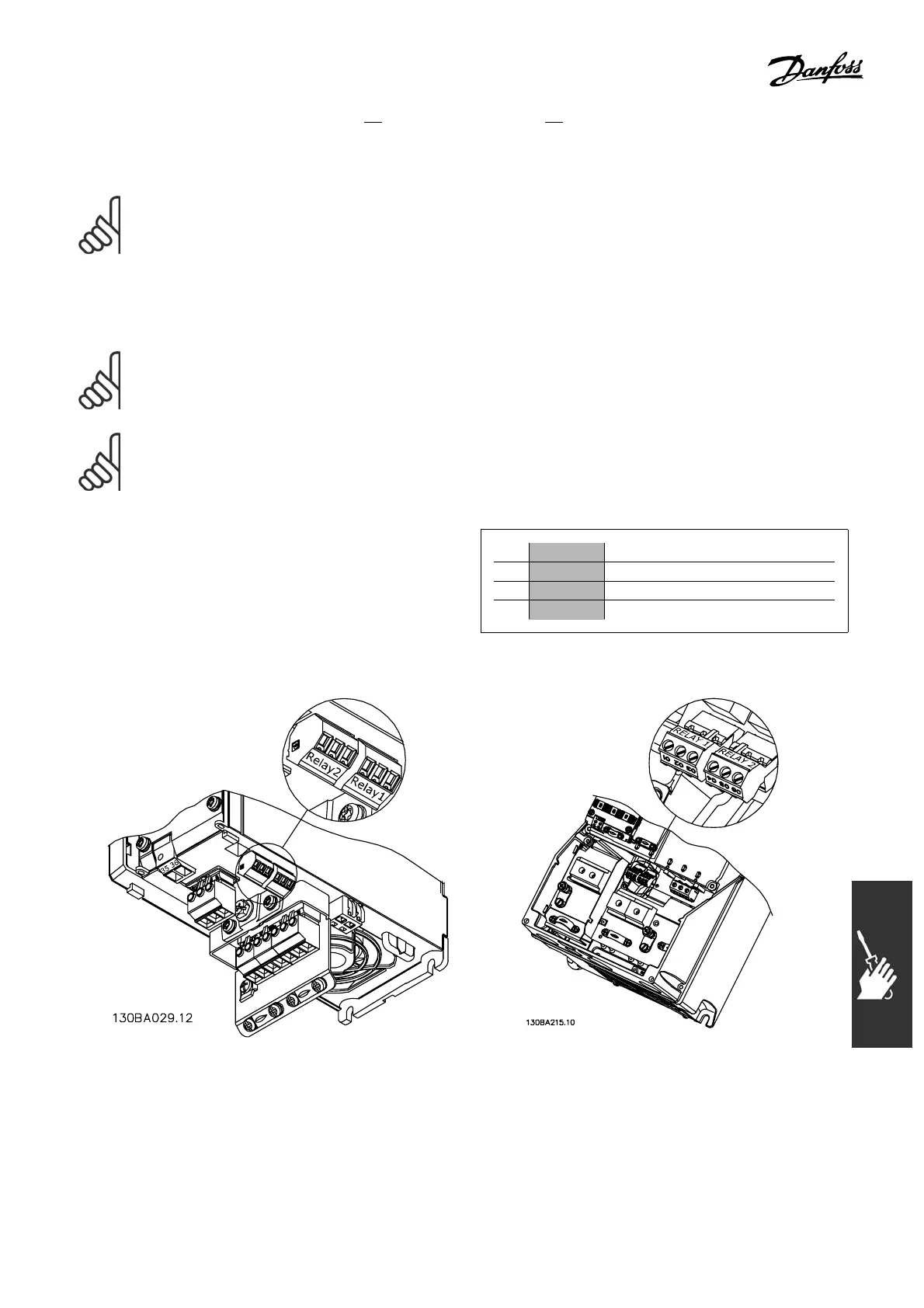
" Relay Connection
To set r elay output, see par. group 5-4* Relays.
No. 01 - 02 make (normally open)
01 - 03 break (normally closed)
04 - 05 make (normally open)
04 - 06 break (normally closed)
Terminals for re lay connection (≤ 10 HP [7.5 kW])
(A1, A2 and A3 enclosure s).
Terminals for relay connection (14.75-29.5 HP
[11-22 kW])
(A5, B1 and B2 enclosures).
115
MG.33.B6.22 - VLT is a registered Danfoss trademark