FC 300 Design Guide
Introduction to FC 300
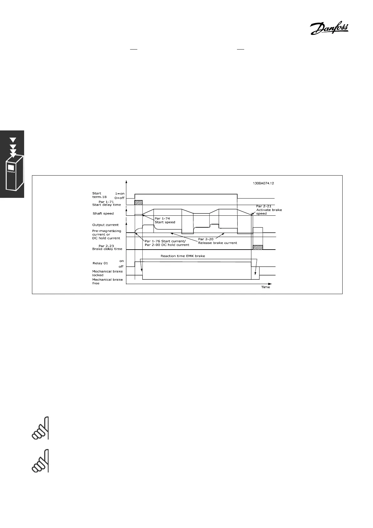
" ControlofMechanicalBrake
For hoisting ap plications, it is necessary to be able to control an electro-magnetic brake. For controlling the
brake, a relay output (relay1 or relay2) or a programmed digital output (terminal 27 or 29) is required.
Normally, this output must be closed for as long as the adjustable frequency drive is unable to ’hold’ the
motor, e.g., beca use of load that is too large. In p ar. 5-40 (Array parameter), par. 5-30, or par. 5-31 (digital
output 27 or 29), select mec h anical brake control [3 2] for applications with an electro-magnetic brake.
When mechanical brake co ntrol [32] is selected, the mechanical brake relay stays closed during the start
until the output current is above the level selected in par. 2-20 Release B rake Current.Duringstop,
the mechanical brake will close when the speed is below the level selected in par. 2-21 Activate Brake
Speed [RPM]. If the adjustable frequency drive is brought into an alarm cond ition, i.e., an overvoltage
situation, the mechanical brake immediately cuts in. This is a lso the case during safe
stop.
Step-by-step Description
In hoisting/low ering applications, it m ust be possible to control an electro-mechanical brake.
• To control the mechanical brake, any relay output or digital output (terminal 27 or 29)
can be used; if nec essary use a suitable magne tic contactor.
• Ensure that the output stays voltag e-fre e as long as the adjustable freq u ency drive is
unable to drive the m otor, for example, due to the load being too heavy or due to the
fact that the motor has not yet been dismounted.
• Select Mechanical brake control [32] in par. 5-4* (or in par. 5-3*) before connecting the mechanical brake.
• The brake is released when the motor current exceeds the preset value in par. 2-20.
• The brake is engaged when the output frequency is less than the frequency set in par. 2-21 or
2-22 and only if the adjustable frequency drive carries out a stop command.
NOTE
Check that the brake resistor is rated for 410 V (240 V units), 820 V (480 V units), 850 V (500
V units) or 975 V (600 V units) - unless Danfoss brake resistors are used.
NOTE
Do not touch the brake resis tor since it can get very hot during/after braking.
50
MG.33.B6.22 - VLT is a registered Danfoss trademark