FC 300 Design Guide
FC 300 Selection
" 24 V Bac k-U p Opt ion (Op tion D)
External 24 V DC Supply
An external 2 4 V DC supply can be installed for low-voltage supply to the control card and any option card
installed. This enables full operation of the LCP (inc luding the parameter setting) without connection to line.
External 24 V DC supply specification:
Input voltage range ...................................................................... 24 V DC +15 % (max. 37 V in 1 0 s)
Max. input current .................................................................................................................. 2.2 A
Max cable length .......................................................................................................... 246 ft (75m)
Input capacitance load ......................................................................................................... < 10uF
Power-up delay .................................................................................................................... < 0.6 s
The inputs are protected.
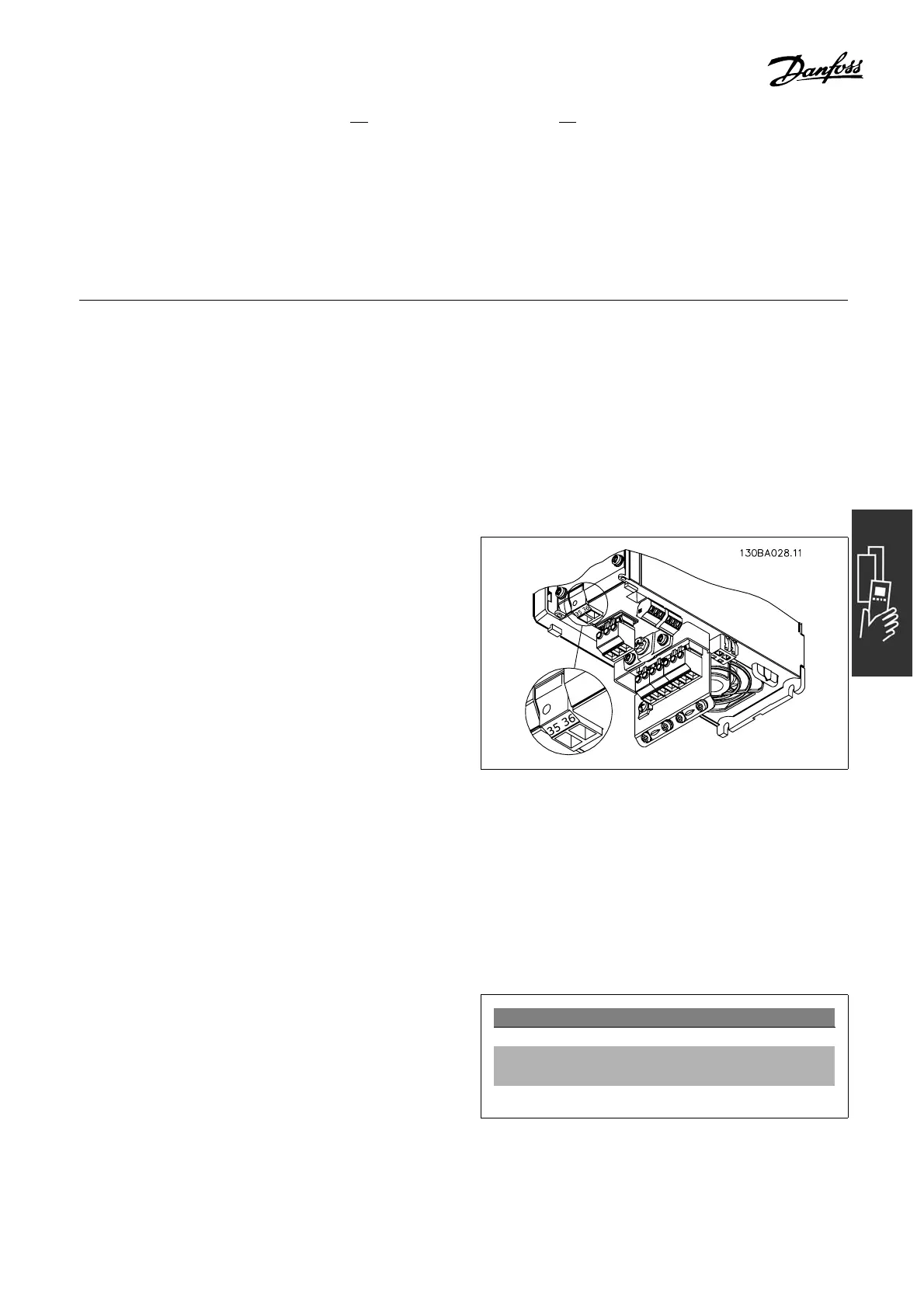
Te rminal numbers:
Terminal 35: - external 24 V DC supply.
Terminal 36: + externa l 24 V DC supply.
Follow these steps:
1. Remove the LCP or Blind Cover
2. Remove the Terminal Cover
3. Remove the Cable Decoupling Plate and
the plastic cover underneath
4. Insert the 24 V DC Back-up External Supply
Option in the Opt ion Slot
5. Mount the Cable Decoupling Plate
6. Attach the Terminal C over and the LCP
or Blind C over.
When MCB 107, 24 V back-up option is supplying
the control circuit, the internal 24 V supply
is autom a tically disconnected.
Connection to 24 V backup supplier.
"
Brake Resistors
Brakeresistorsareusedinappli
cations where high dynamics are needed or a high inertia load has to be
stopped. The brake resistor is used to remove the e nergy from the DC link in the adjustable frequency drive.
Code numb ers for brake resistors: See section How to Order .
" Remote mounting Kit for LCP
TheLocalControlPanelcanbemovedtothefront
of a cabinet by usi
ng the remote build-in kit. The
enclosure is the IP 65. The fastening screws m ust
be tightened with a torq ue of max. 1 Nm.
Technical data
Enclosure: IP 65 fron t
Max. cable length between VLT and
unit: 9.8 ft (3 m)
Communication std: RS-485
81
MG.33.B6.22 - VLT is a registered Danfoss trademark