FC 300 Design Guide
Introduction to FC 300
" Tuning guidelines
The following tuning guidelines are relevant when using one of the Flux motor control principles in
applications w h ere the load is mainly inertial (with a low amount of friction).
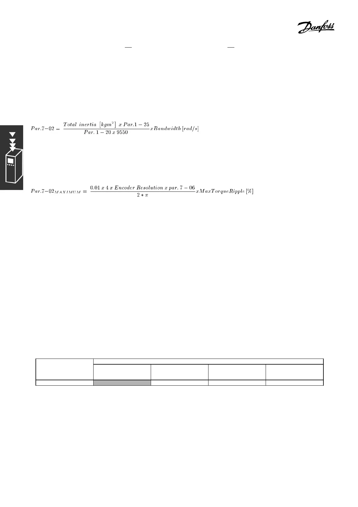
The value of par. 7- 02 Speed PID Proportional Gain is dependent on the combined iner tia of the motor
and load, and the selected bandwidth can be calculated using the fol lowi ng formula:
Note: Par. 1-20 is the motor power in [kW] (i.e. enter ’4’ kW instead of ’4000’ W in the formula). A practical
value for the B andw idth is 20 rad/s. Check the result of the par. 7-02 calculation against the following
formula (not required if you are using a high resolution feedback such as a SinCos feedback):
A good start value for par. 7-06 Speed PID Lowpass Filter Time is 5 ms (lower encoder resolution calls for a
higher filter value). Typical ly a Max Torque Rip ple of 3 % is acceptable. For incremental encoders, the Encod er
Resolution is found in either par. 5-70 (24V HTL on standard drive) or par. 17-11 (5V TTL on MCB102 Option).
Generally the practical maximum limit of par. 7-02 is determ ined by the encoder resolution and the feedback
filter time but other factors in the application might limit par. 7-02 Speed PIDProportional Gain to a lower value.
To minimize overshoot, par. 7-03 S pe ed PIDIntegral Time could be set to ap-
prox. 2.5 s (varies with the application).
Par. 7-04 Speed PID Differentiation Time should be set t o 0 until everything else is tuned. If necessary,
finish the tuning by experimenting with small increments of this setting .
" Process PID Control
The Process PID Control can be used to control application parameters that can be measured by a sensor (i.e.
pressure, temperature, flow) and affected by the connec ted motor through a pump, fan or otherwise.
The table shows the control configurations where Process Control is possible. When a Flux Vector
motor control principle is used, take care also to tune the Speed Control PID parameters. Refer to
the section about the Control Structure to see where the Speed Control is active.
Par. 1-01 Motor Control PrinciplePar. 1-00
Configuration
Mode
U/f VVCplus Flux sens orless Flux w motor feedb
[3] Process N.A. Process Process & Sp eed Process & Spe ed
Note: The Process Control PID will w ork under the default parameter s etting, but tuning the
parameters is highly recommend ed to optimize the application cont rol pe rformance. The two
Flux motor control principles are specially dependent on proper S peed Control PID tuning (prior
to tuning the Proce ss Control PID) to yield their full potential.
34
MG.33.B6.22 - VLT is a registered Danfoss trademark