FC 300 Design Guide
Introduction to FC 300
" Selection of Brake Resistor
To handle higher demands by generatoric braking, a brake resistor is necessary. Using a brake resistor
ensures that the energy is absorbed in the brake resistor and not in the adjustable f re quency drive.
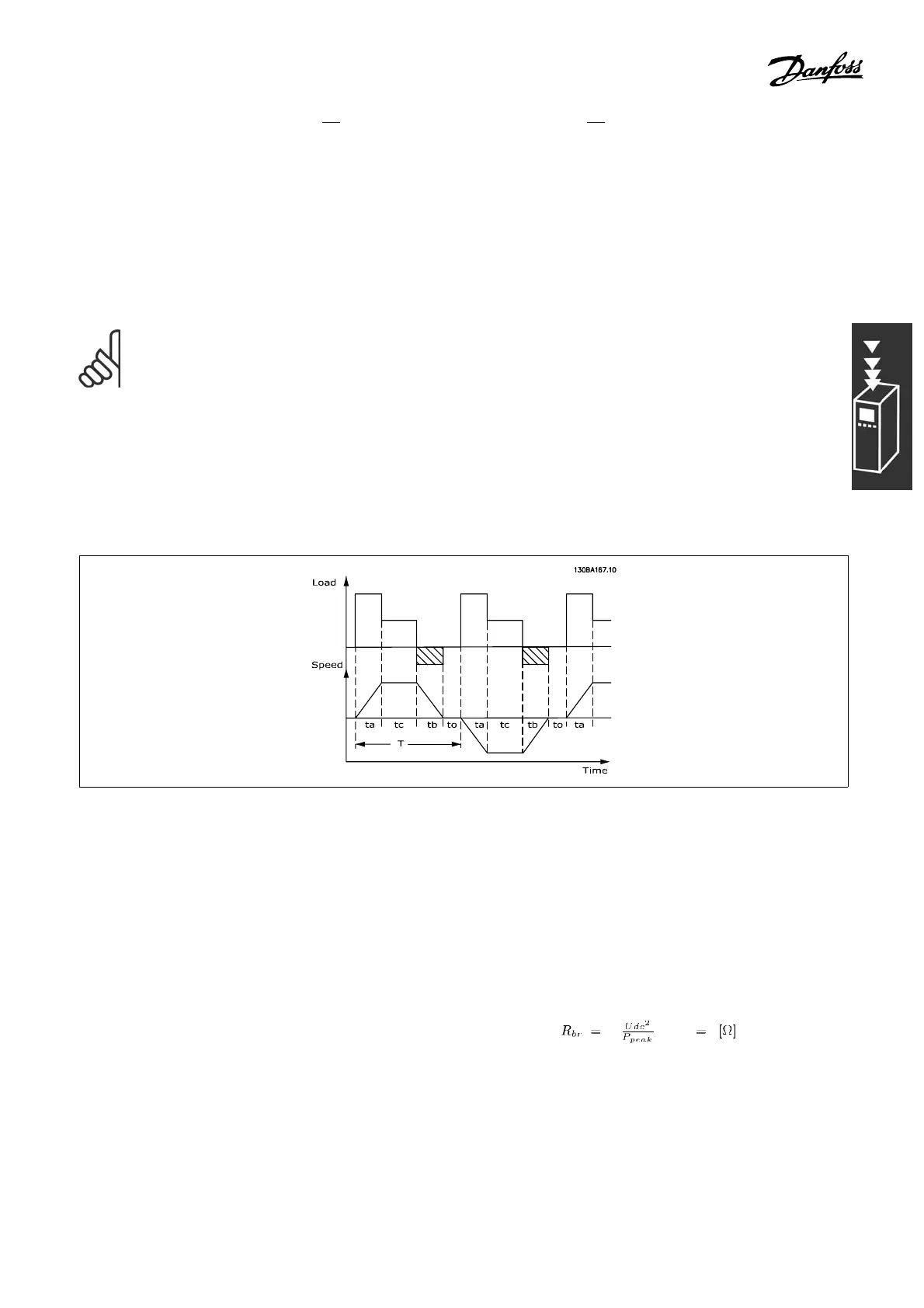
If the amount of kinetic energy transferred to the resistor in each braking period is not known;
the average power can be calculated on the basis of the cycle tim e and braking time, also called
intermitted duty cycle. The resistor intermittent duty cycle is an indication of the duty cycle at
which the resis tor is active. The below figure shows a typical braking cycle.
NOTE
Motor supplie rs often u se S5 when stating the permissible load which is an
expression of intermittent duty cycle.
The intermittent duty cycle for the resistor is calculated as follows:
Duty cycle = t
b
/T
T = cycle time in seconds
t
b
is the braking time in seconds (of the cycle time)
Danfoss offers brake resistors with duty cycle of 5%, 10% and 40%. If a 10% duty cycle is
applied, the brake resistors are able to absorb braking energy for 10% of the cycle time. The
remaining 90% of the cycle time w ill b e used for de f lecting excess heat.
The max. permissible load on the brake resistor is stated as a peak power at a given
intermittent duty cycle and can be calculated as:
P
PEAK
=P
MOTOR
xM
BR(%)
x η
MOTOR
x η
VLT
[W]
The brake resistance is c alculate d as shown:
As can be seen, the brake resistance depends on the intermediate circuit voltage (UD C ).
The FC 301 and FC 302 brake function is settled in 3 areas of the line supply:
47
MG.33.B6.22 - VLT is a registered Danfoss trademark