FC 300 Design Guide
Introduction to FC 300
Size Brake active Warning before cut out Cut out (trip)
FC 301 / 302 3 x 200-240 V 390 V (UDC) 405 V 410 V
FC 301 3 x 380-480 V 778 V 810 V 820 V
FC 302 3 x 380-500 V 810 V 840 V 850 V
FC 302 3 x 525-600 V 943 V 965 V 975 V
NOTE
Check that the brake resistor can cope with a voltage of 410 V, 820 V, 850 V or
975 V - unless Danfoss brake resistors are used.
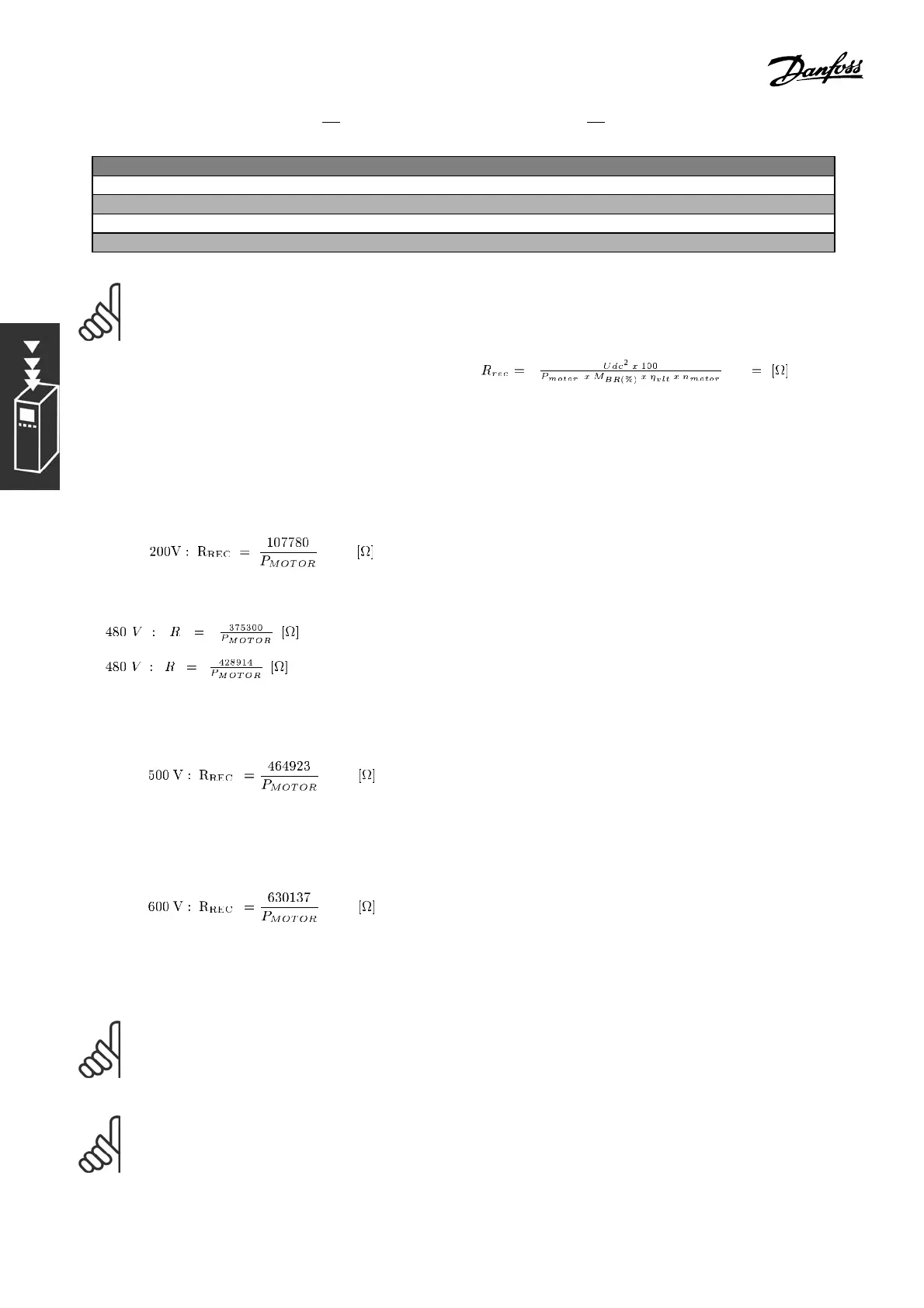
Danfoss recommends the brake resistance R
REC
,i.e.
one that guarantees that the adjusta
ble frequency
driveisabletobrakeatthehighestbrakingtorque
(M
br
)of160%. Theformulacanbewrittenas:
η
motor
is typically at 0.90 η
VLT
is typically at 0.98
For the 200 V, 48 0 V, 500 V and 600 V adjusta ble frequency drives, R
REC
at 160% braking torque is written as:
1.
2.
1. For FC 300 adjustab le freque n cy drives ≤ 10 HP [7.5 kW] shaft output
2. For FC 300 adjustab le frequency drives > 10 HP [7.5 kW] shaft output
NOTE
The resistor brake circuit r esistance selected should not be higher than that recommended by
Danfoss. If a brake resistor with a higher ohmic value is selected, the 160% braking torque may not
be achieved because there is a risk that the adjustable frequency drive cuts out for safety reasons.
NOTE
If a short circuit in the brake transistor occurs, power dissipa tion in the brake resistor is only
prevented by u sing a line s witch or contactor to disconnect the AC line for the adjustab le frequency
drive. (The contactor can be controlle d by the adjustable frequency drive).
48
MG.33.B6.22 - VLT is a registered Danfoss trademark