FC 300 Design Guide
How to Program
" Parameters: Analog In/Out
" 6-** Analog In/Out
Parameter group for configuring the analog
input and output.
" 6-0* Analog I/O Mode
Parameter group for setting up the analog
I/O c onfiguration.
FC 300 is equipped with 2 analog inputs: Terminal
53 and 54. The analog inputs on FC 302 can
freely be allocated to either voltage (-10 V - +10
V) or current input (0/4 - 20 mA)
NOTE
Thermistors may be connected to either
an analog or a digital input.
6-00 Live Zero Time out Time
Range:
1-99s
*
10s
Function:
Enter the Live Zero Time-out time period. Live
Zero Time-out Time is active for analog inputs, i.e.
terminal 53 or terminal 54, alloca ted to curre nt
and used as reference o r feedback sources. If the
reference signal value associated with the selected
current input falls b elow 50% of the value set in par.
6-10, par. 6-12, par. 6-20 or par. 6-22 for a time
period longer than the tim e set in par. 6-00, the
function selected in pa r. 6-01 will be activated.
6-01 Live Zero T imeout Function
Option:
*
Off [0]
Freeze Out put [1]
Stop [2]
Jogging [3]
Max. speed [4]
Stop and trip [5]
Function:
Select the timeout function. The function set in
par. 6-01 will be activated if the input signal on
terminal 53 or 54 is below 50% of the v
alue in par.
6-10, par. 6-12, par. 6-20 or par. 6-22 for a time
period defined in par. 6-00. If several timeouts
occur simultaneously, the a d
justable frequency
drive pr ioritizes the timeout functions as follows:
1. Par. 6-01 Live Zero Timeout Function
2. Par. 5-74 Encoder Loss Function
3. Par. 8-04 Control w ord Timeout Function
The output frequen cy of the adjustable
frequency drive can be:
The output frequency of the adjustable
frequency d rive can be:
• [1] frozen at the present value
• [2] overruled to stop
• [3] overruled to jog speed
• [4] overruled to max. speed
• [5] overruled to stop with subsequent trip
This parameter cannot be adjusted while
the motor is running.
" 6-1* Analog Input 1
Parameters for configuring the scaling and limits
for analog input 1 (terminal 53).
6-10 Terminal 5 3 Low Voltage
Range:
-10.0 - par. 6-11
*
0.07 V
Function:
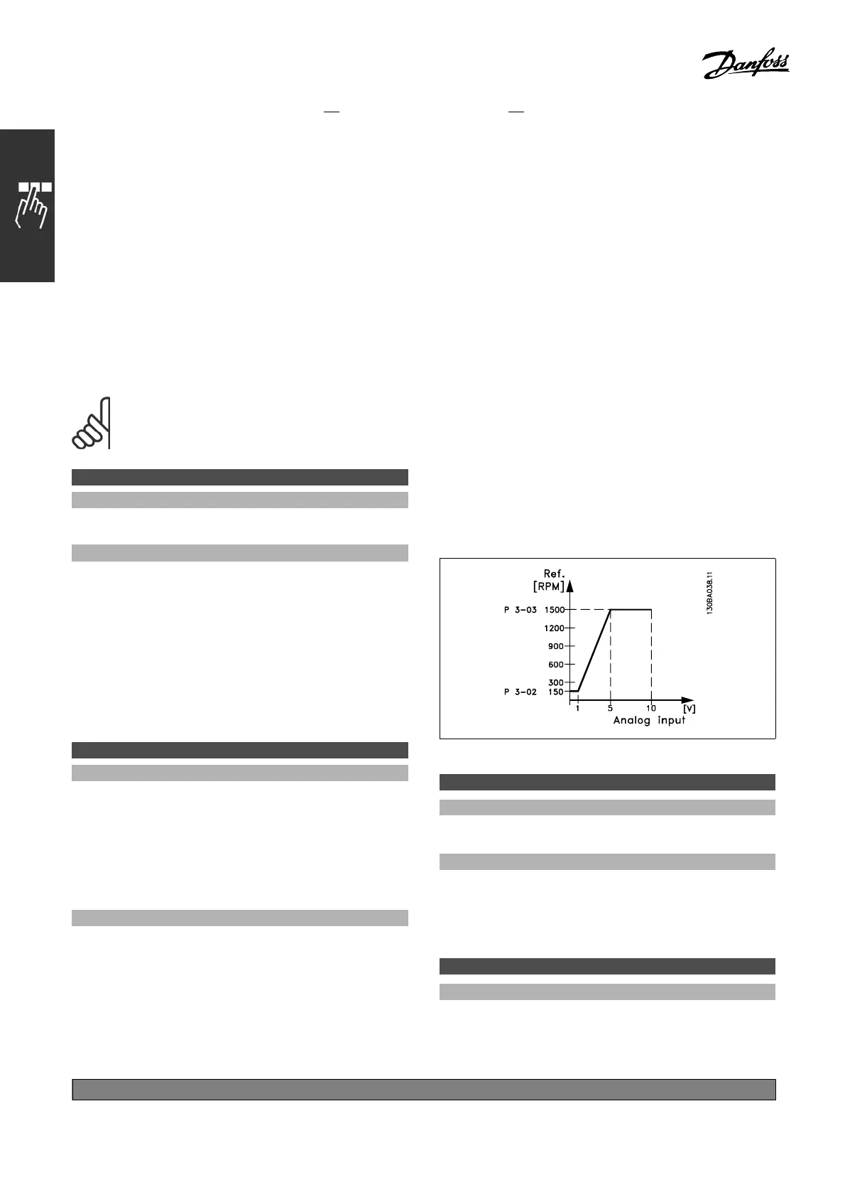
Enter the low voltage value. This analog input
scaling value s ho uld correspond to the minimum
reference value, set in par. 3-02. See also
the section Reference Handling.
6-11 Termin al 53 H igh Volt age
Range:
Par. 6-10 to 10.0 V
*
10.0V
*
default setting ()display text []value for use in communication via serial communication port
202
MG.33.B
6.22 - V LT is a registered Danfoss trademark