FC 300 Design Guide
How to Program
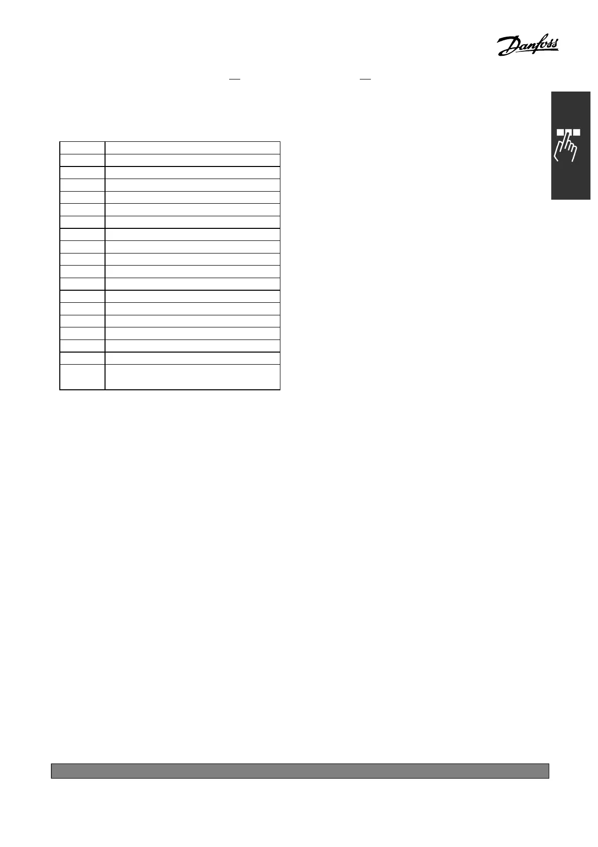
A logical ’0’ indicates that the output is
low or inactive.
Bit 0 CC Digital Output Terminal 27
Bit 1 CC Digital Output Terminal 29
Bit 2 GPIO Digital Output Terminal X 30/6
Bit 3 GPIO Digital Output Terminal X 30/7
Bit 4 CC Relay 1 output terminal
Bit 5 CC Relay 2 output terminal
Bit 6 Option B Relay 1 output terminal
Bit 7 Option B Relay 2 output terminal
Bit 8 Option B Relay 3 output terminal
Bit 9-15 Reserved for future terminals
Bit 16 Option C Relay 1 output terminal
Bit 17 Option C Relay 2 output terminal
Bit 18 Option C Relay 3 output terminal
Bit 19 Option C Relay 4 output terminal
Bit 20 Option C Relay 5 output terminal
Bit 21 Option C Relay 6 output terminal
Bit 22 Option C Relay 7 output terminal
Bit 23 Option C Relay 8 output terminal
Bit
24-31
Reserved for future terminals
*
default setting ()display text []value for use in communication via serial communication port
201
MG.33.B
6.22 - V LT is a registered Danfoss trademark