FC 300 Design Guide
How to Program
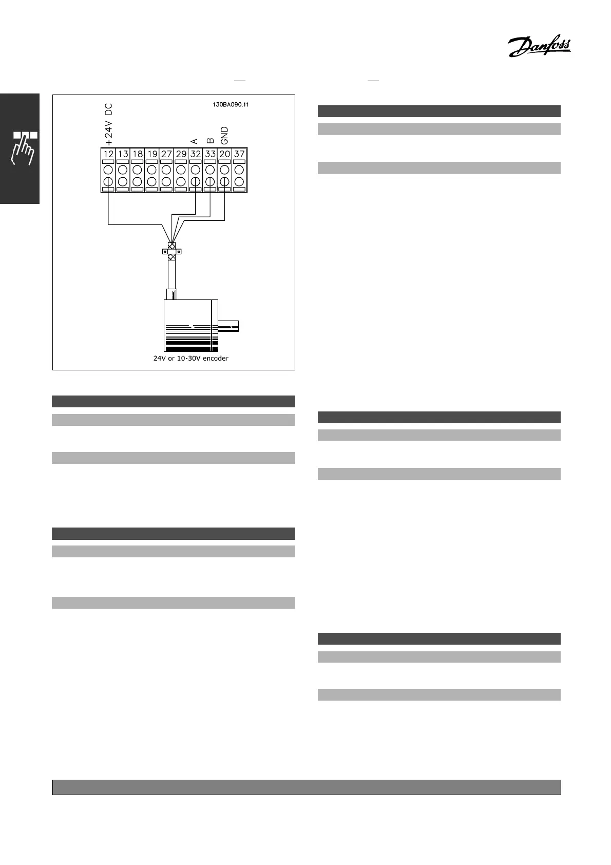
5-70 Term 32/33 Pulses per Revolution
Range:
128 - 4096 PPR
*
1024 PPR
Function:
Set the encoder pulses per revolution on the motor
shaft. Read the correct value from the encoder.
This parameter cannot be adjusted while
the motor is running.
5-71 Term 32/33 Encoder Direction
Option:
*Clockwise [0]
Counterclockwise [1]
Function:
Change the detected encoder rotation
direction
without changing the wiring to the e ncode r. Select
Clockwise [0] to s et channel A 90° (electrical
degrees) behind channel B upon c
lockwise
rotation of the encoder shaft. Select Counter
clockwise [1] to set channel A 90° (electrical
degrees) ahead of channel B u
pon clockwise
rotation of the encode r shaft.
This parameter cannot be adjusted while
the motor is running.
5-72 Term 32/33 Gear Numerator
Range:
1.0 - 60000 N/A
*
1N/A
Function:
Enter the numerator value for a gear ratio
between encod er and drive shaft. The numerator
corresponds to the encoder shaft and the
denominator corresponds to the drive shaft.
Use this parameter to set a multi plier on the
encoder feedback to compensate a ratio of
encoder turns to motor turns.
Example:
Speed on the encoder shaft = 1 000 RPM and
speed on the drive shaft is 3000 R PM:
Par. 5-72 = 1000 and par. 5-73 = 3000, or
par. 5-7 2 = 1 and par. 5-73 = 3.
If the motor control principle is Flux w motor
feedback [3] in p ar. 1-01, the gear ratio between
motor and encoder must be 1: 1. (No gear).
This parameter cannot be adjusted while
the motor is running.
5-73 Term 32/33 Gear Denominator
Range:
1.0 - 60000 N/A
*
1N/A
Function:
Enter the denominator value for a gear
ratio between encoder and drive shaft. The
numerator correspo nds to the encoder shaft
and the denominator corresponds to the drive
shaft. See also par. 5-72.
This parameter cannot be adjusted while
the motor is running.
" 5-9* Bus Controlled
This parameter group selects d igital and relay
outputs via a serial communica tion b us s etting .
5-90 Digital & Relay Bus Control
Range:
0 - FFFFFF FF
Function:
This parameter holds the state of the digital outputs
andrelaysthatiscontrolledbybus.
A logical ’1’ indicates that the output is h ig h or active.
*
default setting ()display text []value for use in communication via serial communication port
200
MG.33.B
6.22 - V LT is a registered Danfoss trademark

 Loading...


