FC 300 Design Guide
FC 300 Selection
How to add the MCB 105 option:
• Thepowertotheadjustablefrequencydrivemustbedisconnected.
• The power to the live part connections on relay terminals must be disconnected.
• Remove the LCP, the terminal cover, and the LCP f ixture from the FC 30x.
• Fit the M CB 105 option in slot B.
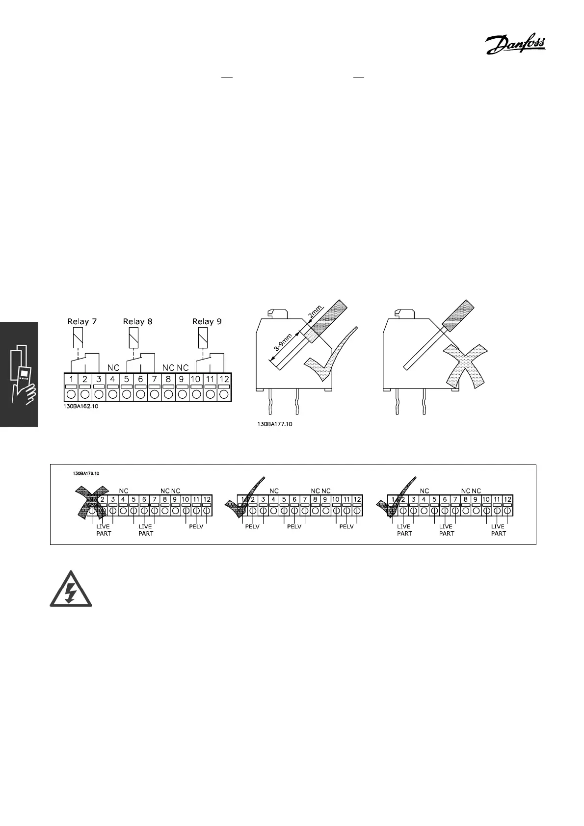
• Connect the control cables and f aste n the cables with the e nclosed cable strips.
• Make sure the length of the stripped wire is correct (see the following drawing).
• Do not mix live parts (high voltage) with control signals (PELV).
• Fit the enla rged LCP fixture and enlarged terminal cover.
• Replace the LCP.
• Connect power to the adjustable frequency d rive.
• Select the relay functions in par. 5-40 [6-8], 5-41 [6-8] a nd 5-42 [6-8].
NB (Array [6] is relay 7, a rray [7] is relay 8, and array [8] is relay 9)
Do not combine low voltage parts and PELV systems.
80
MG.33.B6.22 - VLT is a registered Danfoss trademark