FC 300 Design Guide
How to Program
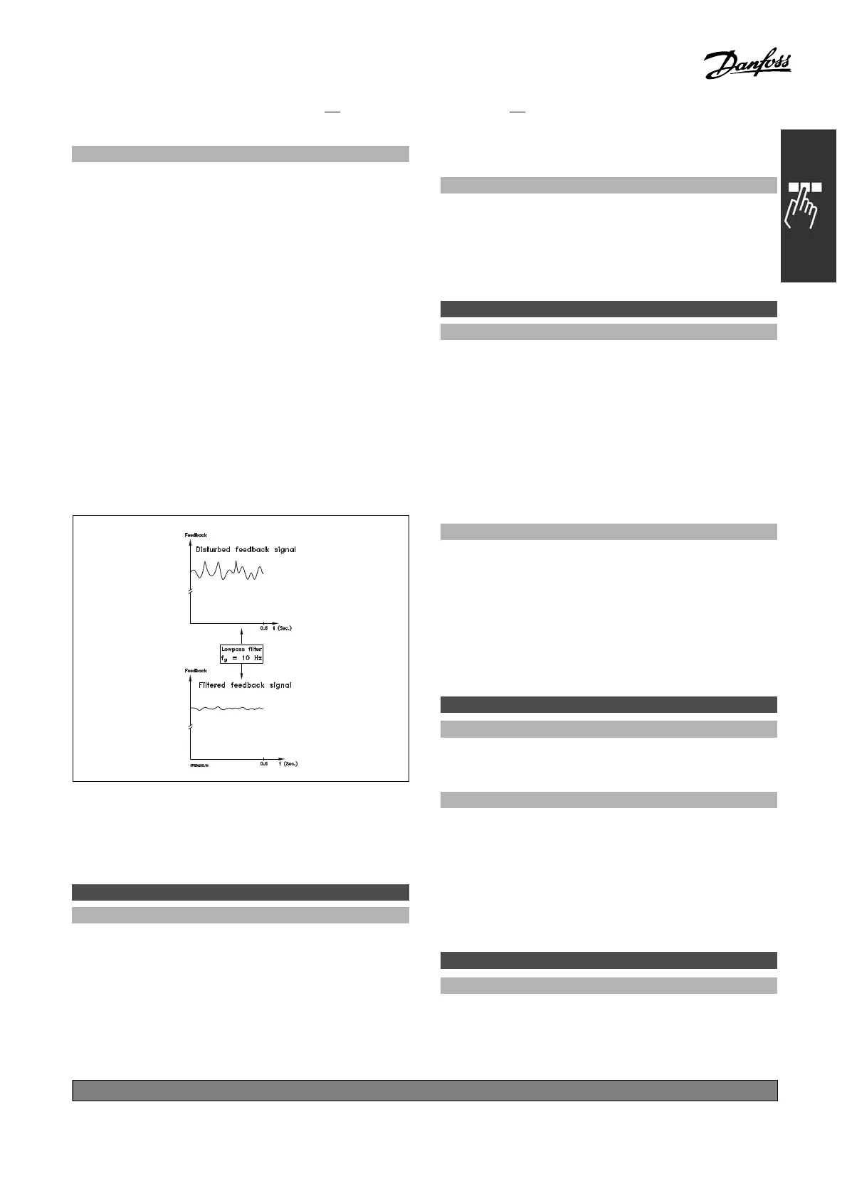
Function:
Set a time constant for the speed control low-pa ss
filter. The low-pass filter improves steady-state
performance and dam pens oscillations on the
feedback signal. Thi s is an advantage if there
is a great amount on noise in the system, see
illustration below. For example, if a time constant
(τ) of 100 ms is programmed, the cut-off frequency
for the low-pass filter w ill be 1/0.1= 10 RAD /sec.,
corresponding to (10/2 x p) = 1.6 Hz. The P ID
regulator only regulates a feedback signal that
varies by a frequency of less than 1.6 Hz. If the
feedback signal varies by a higher frequency than
1.6 Hz, the PID regulator does not react.
Note that severe filtering can be detrimental
to dynam ic performance.
This parameter is used with par. 1-00 Speed
closed loop [1] and Torq ue [2] control.
" 7-2* Process Ctrl. Feedb.
Select the f ee dback sources for the Process PID
Control, and how this feedba ck should b e handled.
7-20 Process CL Fee dback 1 Resource
Option:
*
No function [0]
Analog input 53 [1]
Analog input 54 [2]
Frequency input 29 [3]
Frequency input 33 [4]
Bus feedback 1 [5]
Bus feedback 2 [6]
Analog input X30/11 [7]
Analog input X30/12 [8]
Function:
The effective feedback signal is made up of the
sum of up to two different input signals.
Select which frequency converter input should be
treated as the source of the first of these signals.
The second input signal is defined in par. 7-22.
7-22 Process CL F ee d b ack 2 Resource
Option:
*
No function [0]
Analog input 53 [1]
Analog input 54 [2]
Frequency input 29 [3]
Frequency input 33 [4]
Bus feedback 1 [5]
Bus feedback 2 [6]
Analog input X30/11 [7]
Analog input X30/12 [8]
Function:
The effective feedback signal is made up of the
sum of up to two different input signals. Select
which frequency converter input should be treated
asthesourceofthesecondofthesesignals. The
first input signal is defined in par. 7-21.
" 7-3* Process PID Ctrl.
Parameters for configuring the P roce ss PID control.
7-30 Process PID No rmal/Inverse Control
Option:
*
Normal [0]
Inverse [1]
Function:
Select Normal [0] to se t the process control
to increase the output frequency.
Select Inverse [1] to set the process con
trol
to reduce the output frequency. Normal and
inverse control are implemented by introducing
a difference between the r efere n c
esignal
and the feedback signal.
7-31 Process PID Anti Windup
Option:
*
Off [0]
On [1]
*
default setting ()display text []value for use in communication via serial communication port
209
MG.33.B
6.22 - V LT is a registered Danfoss trademark

 Loading...


