FC 300 Design Guide
Introduction to FC 300
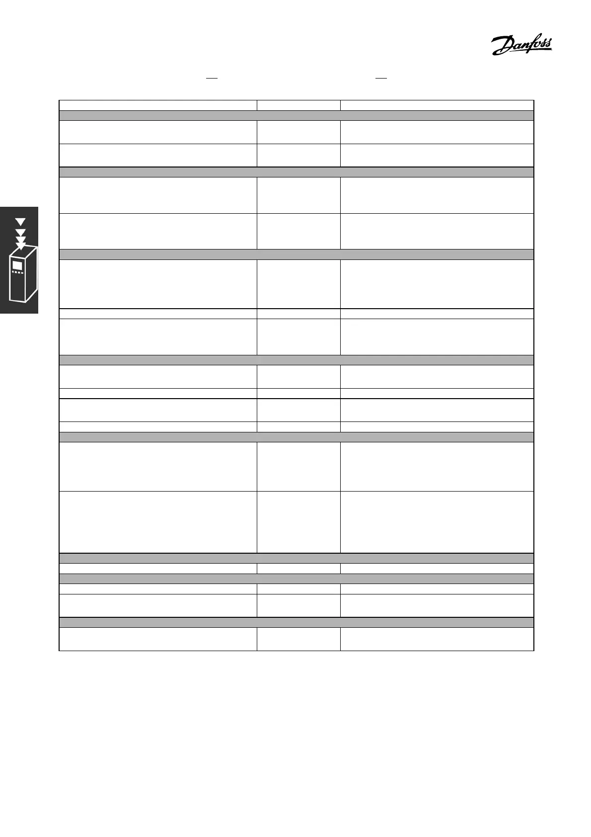
Function Par. no. Setting
1) Make sure the motor runs properly. Do the follo wing:
Set the motor parameters using nam eplate
data
1-2* As specified by motor nameplate
Have the adjustable frequency d rive do an
automatic motor adaptation.
1-29 [1] Enable complete AMA
2) Check that the motor is r u nning in the right direction .
Press the “Hand On” LCP key. Check that the
motor is running and note in which direction
it is turning.
Set a positive reference.
If the motor was turning in the wrong direction,
remove the motor plug and switch two of the
motor phases.
3) M ake sure the adjustable frequency drive limits are set to safe values
Check that the ramp settings are within
capabilities of the adjustable frequency
drive and allowed application operating
specifications.
3-41
3-42
60 sec.
60 sec.
Depends on motor/load size!
Also active in Hand mode.
Prohibit the motor from reversing if necessary 4-10 [0] Clockwise
Set acceptable limits for the motor speed and
frequency
4-11
4-13
4-19
300 RPM
1500 RPM (default)
60 Hz (default 132 Hz)
4) Configure the reference to the process control.
Allow for an “asymmetrical” reference range by
selecting the “Min - Max” refe r ence range.
3-00 [0]Min-Max
Selecttheappropriatereferenceunit. 3-01 [55]°F [[13] °C]
Set acceptable limits for the sum of all
references.
3-02
3-03
23°F [-5°C]
95°F [35°C]
Set up Analog Input 53 as a reference re source 3-15 Not necessary (default)
5) Scale the analog inputs used for reference and feedback.
Scale the Analog Input 1 (terminal 53) that
is used for t he temperature re f erence via
potentiometer (23° - 95°F [-5° - 35°C], 0-10
VDC).
6-10
6-11
6-14
6-15
0VDC
10 VDC
23°F [-5°C]
95°F [35°C]
Scale the Analog Input 2 (terminal 54) that
is used for the temperature feedback via
transmitter (14°-104°F [-10° - 40°C], 4-20
mA).
6-22
6-23
6-24
6-25
6-26
4mA
20 mA
14°F [-10°C]
104°F [40°C]
50 ms - 100 ms
6) Configure th e feedback to the process control.
Set up Analog Input 54 as a feedback resource 7-20 [2] Analog input 54
7) Tune the process control PID parameters.
Select inverse control. 7-30 [1] Inverse
Use the tuning guidelines when relevant or
tune ma nually.
7-3* See the guidelines below
8) Finished!
Save the p arameter settings to the LCP for
safekeeping.
0-50 [1] All to LCP
38
MG.33.B6.22 - VLT is a registered Danfoss trademark
 Loading...


