8 I/O and Hardware Menu
8.1 Basic I/O
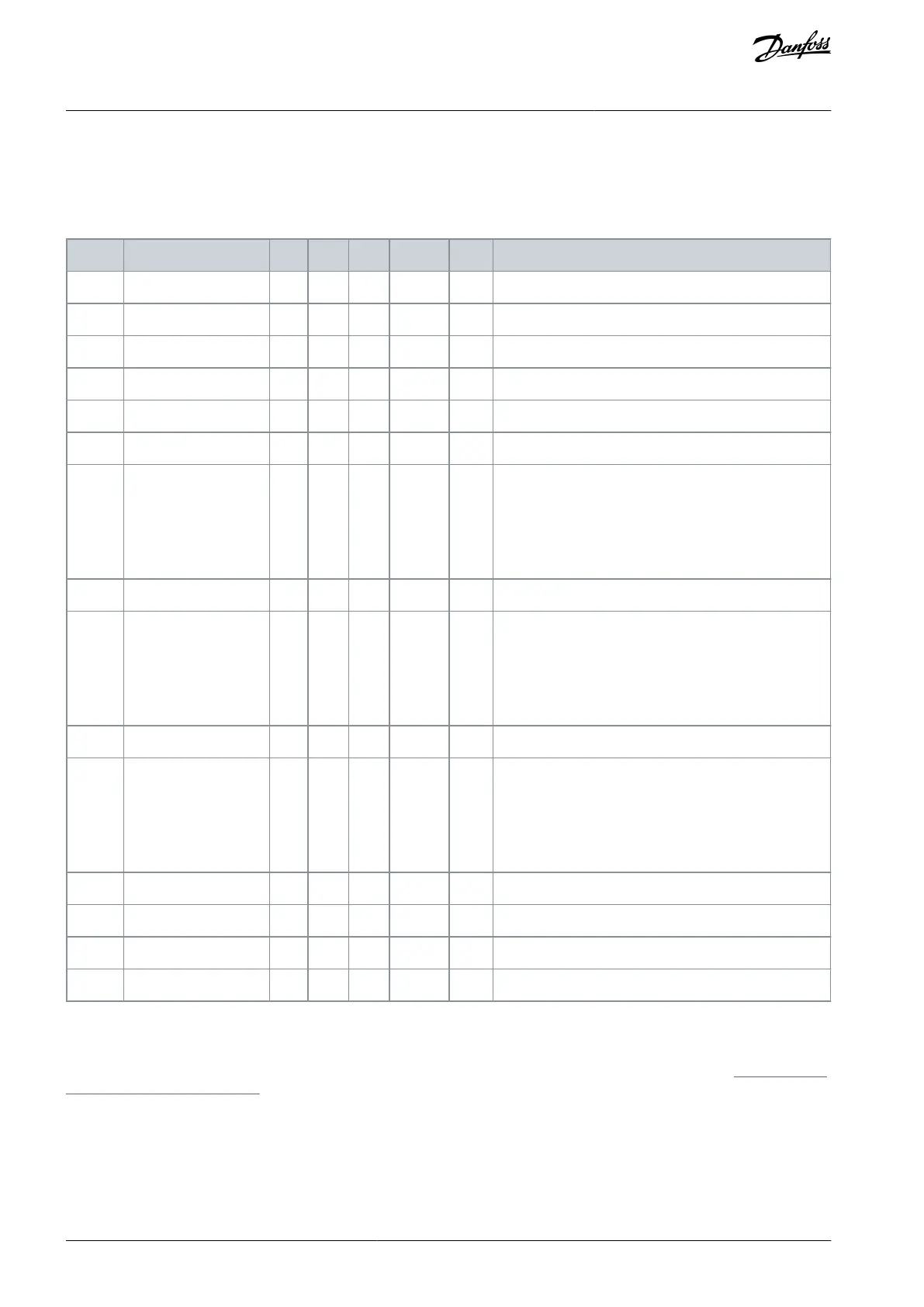
Table 112: The Basic I/O Parameters in the I/O and Hardware Menu
Status of the digital input signal
Status of the digital input signal
Status of the digital input signal
Status of the digital input signal
Status of the digital input signal
Status of the digital input signal
Shows the mode that is set for the analog input signal.
The selection is made with a DIP switch on the control
board.
1 = 0...20mA
3 = 0...10V
Status of the analog input signal
Shows the mode that is set for the analog input signal.
The selection is made with a DIP switch on the control
board.
1 = 0...20mA
3 = 0...10V
Status of the analog input signal
Shows the mode that is set for the analog input signal.
The selection is made with a DIP switch on the control
board.
1 = 0...20mA
3 = 0...10V
Status of the analog output signal
Status of the relay output signal
Status of the relay output signal
Status of the relay output signal
8.2 Option Board Slots
The parameters in this menu are different for all the option boards. The parameters of the installed option board is shown. If there is
no option board in the slots C, D or E, no parameters are shown. See more about the location of the slots in chapter 11.7.1.1 General
Information on the Programming.
When an option board is removed, the fault code 39 and the fault name Device removed show on the display.
AB298035655957en-000201 / DPD01083140 | Danfoss A/S © 2023.08
I/O and Hardware Menu
VACON® 100 FLOW
Application Guide

 Loading...

