8.5 Power Unit Settings
In this menu, the settings of the fan, the brake chopper, the sine filter, and the harmonic filter can be changed.
The fan operates in the optimized or the always on mode. In the optimized mode, the internal logic of the drive receives data about
the temperature and controls the fan speed. After the drive goes in the Ready state, the fan stops in 5 minutes. In the always on
mode, the fan operates in full speed, and does not stop.
The sine filter keeps the overmodulation depth in limits and does not let the thermal management functions decrease the switching
frequency.
The harmonic filter can be enabled to avoid possible resonances in the DC link of the AC drive.
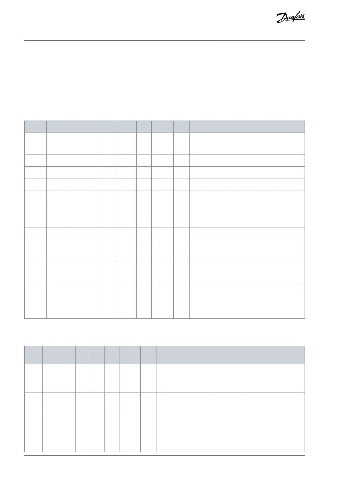
Table 116: Power Unit Settings
0 = Always on
1 = Optimized
Lifetime of the fan of the drive
Alarm limit of the fan lifetime
Reset the fan lifetime counter with this button.
0 = Disabled
1 = Enabled (Run)
2 = Enabled (Run & Stop)
3 = Enabled (Run, no testing)
Use this parameter to enable fast rise in estimated
supply voltage.
0 = Disabled
1 = Enabled
8.6 Keypad
Table 117: The Keypad Parameters in the I/O and Hardware Menu
The time after which the display goes back to the page that is set
with parameter P5.7.2.
0 = Not used
The page that the display shows when the drive is powered up, or
when the time that is set with P5.7.1 is expired. If the value is set to
0, the display shows the last page that it showed.
0 = None
1 = A menu index
2 = Main menu
3 = Control page
AB298035655957en-000201 / DPD01083142 | Danfoss A/S © 2023.08
I/O and Hardware Menu
VACON® 100 FLOW
Application Guide

 Loading...

