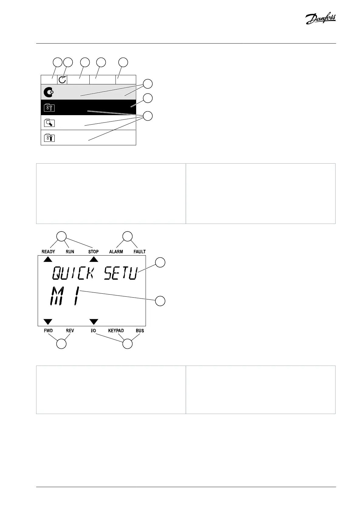
Illustration 3: Graphical Display of the Control Panel
The first status field: STOP/RUN
The rotation direction of the motor
The second status field: READY/NOT READY/FAULT
The control place field: PC/I/O/KEYPAD/ FIELDBUS
The location field: the ID number of the parameter
and the current location in the menu
An activated group or item
The number of items in the group in question
Illustration 4: Text Display of the Control Panel
The indicators of alarm and fault
The name of the group or item of the current loca-
tion
The current location in the menu
The indicators of the control place
The indicators of the rotation direction
2.2 Menu Structure
The data of the AC drive is in menus and submenus. To move between the menus, use the arrow buttons Up and Down in the
keypad. To go into a group or an item, push the [OK] button. To go back to the previous level, push the [BACK/RESET] button.
On the display, current location in the menu shows, for example M3.2.1. The display also shows the name of the group or item in the
current location.
AB298035655957en-000201 / DPD01083 | 15Danfoss A/S © 2023.08
User Interfaces
VACON® 100 FLOW
Application Guide

 Loading...

