EasyManuals Logo

Danfoss VACON 100 FLOW Series User Manual

Danfoss VACON 100 FLOW Series
334 pages
To Next Page IconTo Next Page
To Previous Page IconTo Previous Page
Page #81 background imageLoading...
Page #81 background image
Index
Monitoring value
Unit
Scale
ID
Description
V2.6.11
Last active alarm code
1
74
V2.6.12
Last active alarm ID
1
94
V2.6.13
Motor regulator status
1
77
B0 = Current Limit (Motor)
B1 = Current Limit (Generator)
B2 = Torque Limit (Motor)
B3 = Torque Limit (Generator)
B4 = Overvoltage Control
B5 = Undervoltage Control
B6 = Power Limit (Motor)
B7 = Power Limit (Generator)
V2.6.14
Motor Shaft Power 1 Decimal
kW/hp
98
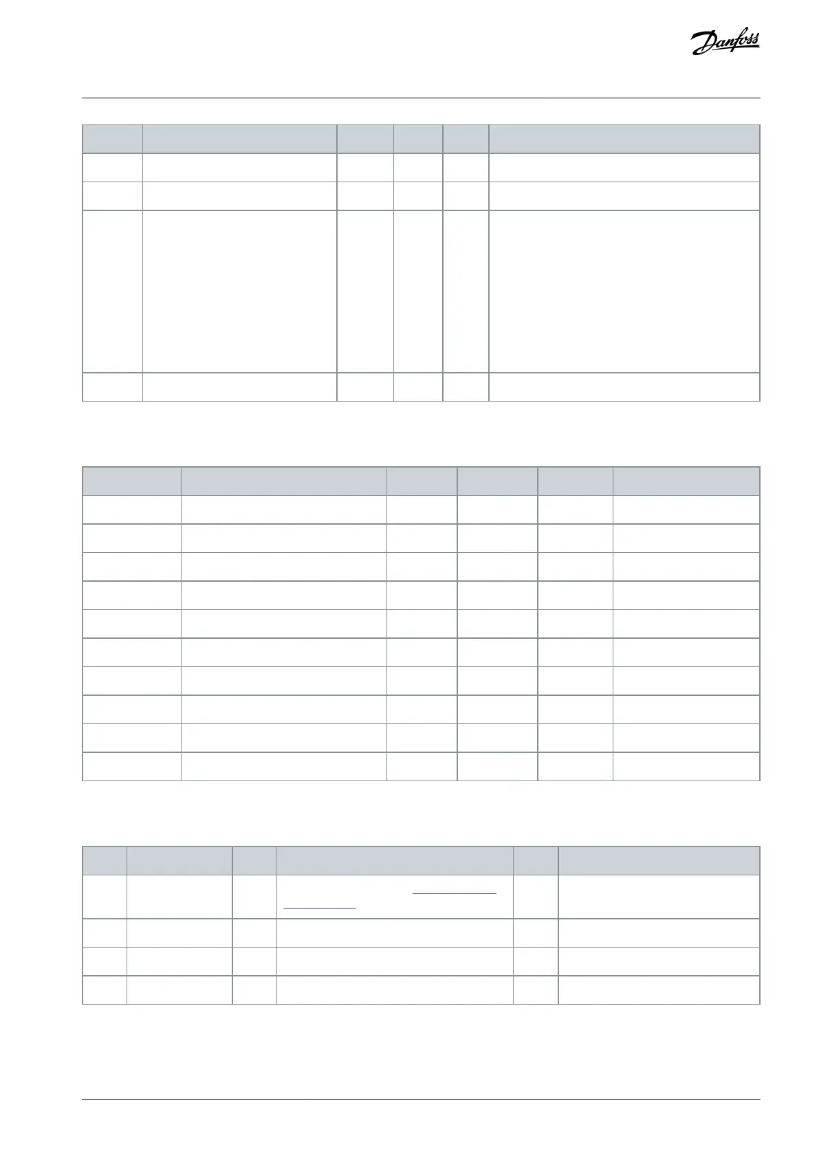
5.8 Timer Functions Monitoring
Table 18: Monitoring of the Timer Functions
Index
Monitoring value
Unit
Scale
ID
Description
V2.7.1
TC 1, TC 2, TC 3
1
1441
V2.7.2
Interval 1
1
1442
V2.7.3
Interval 2
1
1443
V2.7.4
Interval 3
1
1444
V2.7.5
Interval 4
1
1445
V2.7.6
Interval 5
1
1446
V2.7.7
Timer 1
s
1
1447
V2.7.8
Timer 2
s
1
1448
V2.7.9
Timer 3
s
1
1449
V2.7.10
Real-time clock
1450
5.9 PID Controller Monitoring
Table 19: Monitoring of the Values of the PID Controller
Index
Monitoring value
Unit
Scale
ID
Description
V2.8.1
PID setpoint
Varies
As is set in P3.13.1.7 (See 6.13 Group 3.13:
PID Controller.)
20
V2.8.2
PID feedback
Varies
As is set in P3.13.1.7
21
V2.8.3
PID Feedback (1)
Varies
As is set in P3.13.1.7
15541
V2.8.4
PID Feedback (2)
Varies
As is set in P3.13.1.7
15542
AB298035655957en-000201 / DPD01083 | 81Danfoss A/S © 2023.08
Monitor Menu
VACON® 100 FLOW
Application Guide

Table of Contents

Questions and Answers:

Question and Answer IconNeed help?

Do you have a question about the Danfoss VACON 100 FLOW Series and is the answer not in the manual?

Danfoss VACON 100 FLOW Series Specifications

General IconGeneral
BrandDanfoss
ModelVACON 100 FLOW Series
CategoryDC Drives
LanguageEnglish

Related product manuals