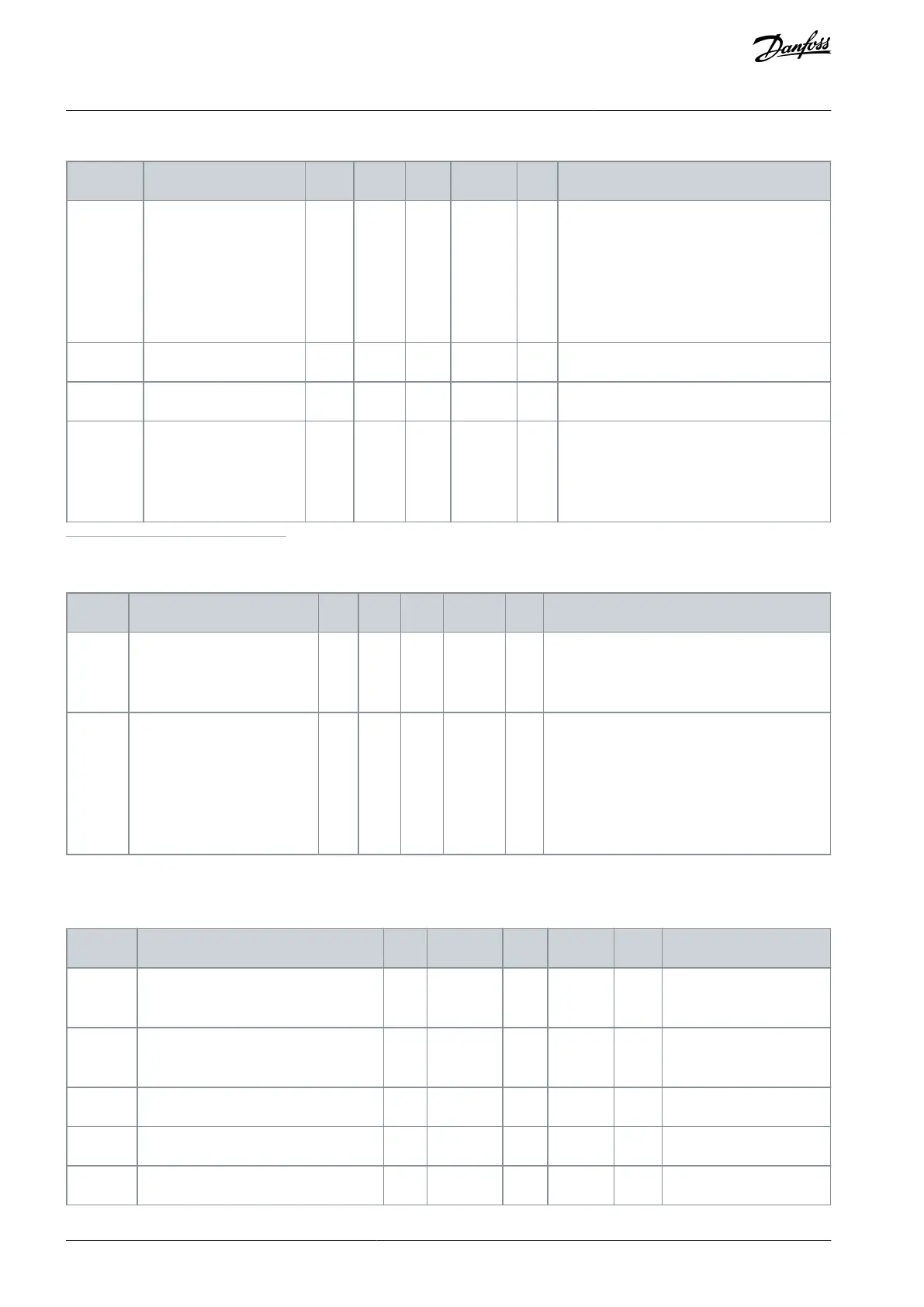
Table 63: Temperature Input Fault 2 Settings
B0 = Temperature Signal 1
B1 = Temperature Signal 2
B2 = Temperature Signal 3
B3 = Temperature Signal 4
B4 = Temperature Signal 5
B5 = Temperature Signal 6
0 = No response
1 = Alarm
2 = Fault (Stop according to stop mode)
3 = Fault (Stop by coasting)
1
Temperature input settings are only available if a B8 or BH option board is installed.
Table 64: AI Low Protection Settings
Analog Input Low Protection
0 = No protection
1 = Protection enabled in Run state
2 = Protection enabled in Run and Stop state
0 = No action
1 = Alarm
2 = Alarm + preset fault frequency (P3.9.1.13)
3 = Alarm + previous frequency reference
4 = Fault (Stop according to stop mode)
5 = Fault (Stop by coasting)
6.10 Group 3.10: Automatic Reset
Table 65: Automatic Reset Settings
0 = Flying start
1 = According to P3.2.4.
AB298035655957en-000201 / DPD01083108 | Danfoss A/S © 2023.08
Parameters Menu
VACON® 100 FLOW
Application Guide

 Loading...

