3 = Fault (Stop by coasting)
Underload Protection: Field Weakening
Area Load
Underload Protection: Zero Frequency
Load
Underload Protection: Time Limit
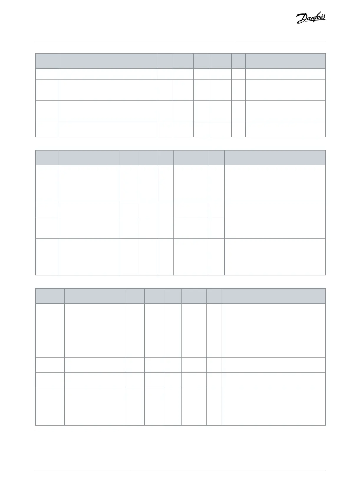
Table 61: Quick Stop Settings
0 = Coasting
1 = Quick stop deceleration time
2 = Stop according to Stop function
(P3.2.5)
Quick Stop Deceleration
Time
Response to Quick Stop
Fault
0 = No action
1 = Alarm
2 = Fault (Stop according to Quick stop
mode)
Table 62: Temperature Input Fault 1 Settings
B0 = Temperature Signal 1
B1 = Temperature Signal 2
B2 = Temperature Signal 3
B3 = Temperature Signal 4
B4 = Temperature Signal 5
B5 = Temperature Signal 6
0 = No response
1 = Alarm
2 = Fault (Stop according to stop mode)
3 = Fault (Stop by coasting)
1
Temperature input settings are only available if a B8 or BH option board is installed.
AB298035655957en-000201 / DPD01083 | 107Danfoss A/S © 2023.08
Parameters Menu
VACON® 100 FLOW
Application Guide

 Loading...

