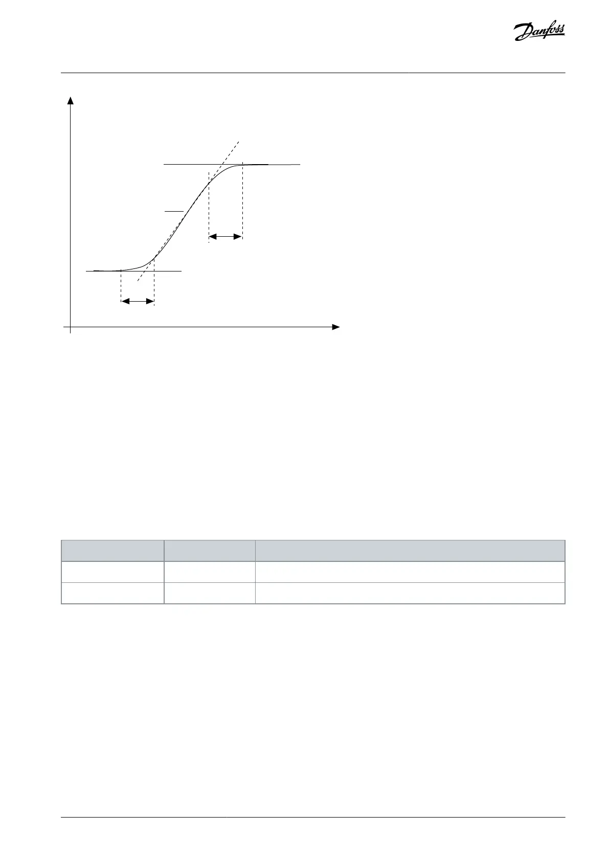
Illustration 49: The Acceleration/Deceleration Curve (S-shaped)
11.6.2.2 (ID 502) Acceleration Time 2
Location in the menu: P3.4.2.2
Use this parameter to set the time that is necessary for the output frequency to increase from zero frequency to maximum frequen-
cy.
11.6.2.3 (ID 503) Deceleration Time 2
Location in the menu: P3.4.2.3
Use this parameter to set the time that is necessary for the output frequency to decrease from maximum frequency to zero frequen-
cy.
11.6.2.4 (ID 408) Ramp 2 Selection
Location in the menu: P3.4.2.4
Use this parameter to select either ramp 1 or ramp 2.
Ramp 1 Shape, Acceleration Time 1, and Deceleration Time 1
Ramp 2 Shape, Acceleration Time 2, and Deceleration Time 2
11.6.2.5 (ID 533) Ramp 2 Threshold Frequency
Location in the menu: P3.4.2.5
Use this parameter to set the output frequency limit above which the Ramp 2 is used.
Use the function, for example, in applications for deep well pumps, where faster ramp times are necessary when the pump starts or
stops (operates below the minimum frequency).
Second ramp times are activated when the output frequency of the drive goes above the limit specified by this parameter. To disa-
ble the function, set the value of the parameter to 0.
AB298035655957en-000201 / DPD01083 | 191Danfoss A/S © 2023.08
Parameter Descriptions
VACON® 100 FLOW
Application Guide

 Loading...

