The drive is always connected to Motor 1. The interlocks do not affect Motor 1. Motor 1 is not
included in the autochange logic.
It is possible to connect the drive to any of the motors in the system. The interlocks affect all
the motors. All the motors are included in the autochange logic.
The connections are different for the parameter values 0 and 1.
Selection 0, Auxiliary pumps
The drive is directly connected to Motor 1. The other motors are auxiliary motors. They are connected to the mains by contactors,
and controlled by relays of the drive. The autochange or the interlock logic does not affect Motor 1.
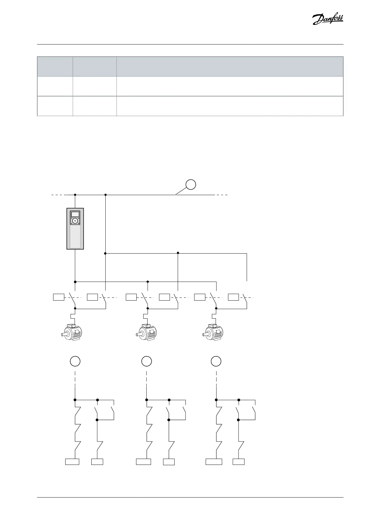
Selection 1, All pumps
To include the regulating motor in the autochange or in the interlock logic, obey the instructions in the following figure. 1 relay
controls each motor. The contactor logic always connects the first motor to the drive, and the next motors to the mains.
K1 K1.1 K2 K2.1 K3 K3.1
K1 K1.1 K2 K2.1 K3 K3.1
K1.1 K1
K2
K3 K2 K3 K3 K1 K3 K1 K2 K1
K2.1 K2
K1
K3.1 K3
K2
M1 M2 M3
Illustration 97: Selection 1
AB298035655957en-000201 / DPD01083 | 263Danfoss A/S © 2023.08
Parameter Descriptions
VACON® 100 FLOW
Application Guide

 Loading...

