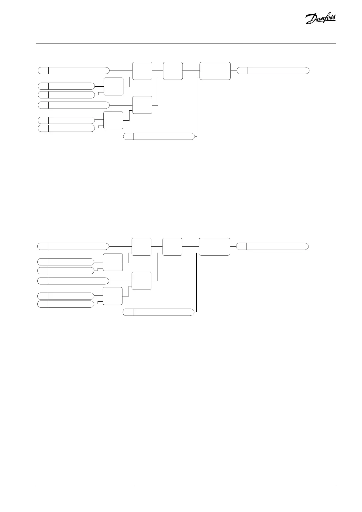
M
PID Feedback
P
Banwidth Delay
Start Aux Pump
V
M
Output Freq
M
PID Setpoint
P
Freq Ref Max
P
Staging Freq
P
Bandwidth
LT
IN1
IN2
GT
IN1
IN2
MIN
IN1
IN2
SUB
IN1
IN2
AND
IN1
IN2
ON-DELAY
IN OUT
TIME
e30bi988.10
Illustration 100: Staging Frequency
11.17.7.2 (ID 15546) Destaging Frequency
Location in the menu: P3.15.22.2
Use this parameter to adjust the output frequency level at which the auxiliary motor starts in the Multi-pump system.
The parameter has no effect, if its value is set below Min Frequency Reference (P3.3.1.1).
By default, an auxiliary pump stops (is destaged), if the PID feedback signal goes above the specified bandwidth area and the pump
that controls the system operates at the minimum frequency.
The auxiliary pump can stop at a higher frequency to get better process values or to use less energy. Then, use the parameter to set
the start frequency of the auxiliary pump above the minimum frequency.
M
PID Feedback
P
Banwidth Delay
Stop Aux Pump
V
M
Output Freq
M
PID Setpoint
P
Freq Ref Min
P
De-Staging Freq
P
Bandwidth
GT
IN1
IN2
LT
IN1
IN2
MAX
IN1
IN2
ADD
IN1
IN2
AND
IN1
IN2
ON-DELAY
IN OUT
TIME
e30bi989.10
Illustration 101: Destaging Frequency
11.17.7.3 (ID 15588) Staging Delay
Location in the menu: P3.15.22.3
Use this parameter to give a delay to start the next auxiliary pump in the Multi-pump system.
When PID feedback value goes below the bandwidth area, the time defined by this parameter must elapse before the next auxiliary
pump is started.
11.17.7.4 (ID 15589) Destaging Delay
Location in the menu: P3.15.22.4
Use this parameter to give a delay to stop auxiliary pump in the Multi-pump system.
When PID feedback value goes above the bandwidth area, the time defined by this parameter must elapse before the next auxiliary
pump is stopped.
11.18 Maintenance Counters
11.18.1 The Maintenance Counters
A maintenance counter tells that maintenance must be done. For example, it is necessary to replace a belt or to replace the oil in a
gearbox. There are 2 different modes for the maintenance counters, hours, or revolutions*1000. The value of the counters increases
only during the RUN status of the drive.
AB298035655957en-000201 / DPD01083 | 269Danfoss A/S © 2023.08
Parameter Descriptions
VACON® 100 FLOW
Application Guide

 Loading...

