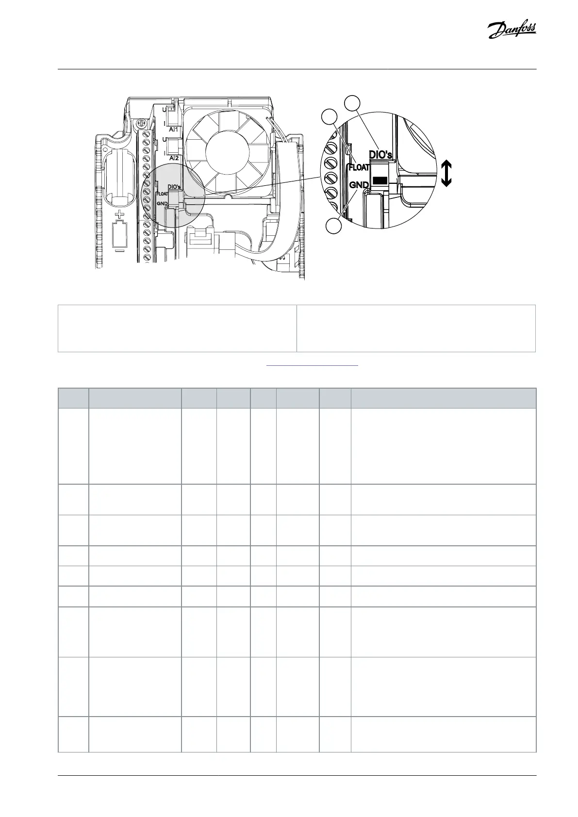
Illustration 7: The DIP Switch
Connected to GND (Default)
See information on the Startup, and Fire mode wizards in 4.2.1 Wizards in Menu 1.1.
Table 3: M1 Quick Setup
0 = Standard
1 = HVAC
2 = PID Control
3 = Multi-pump (single drive)
4 = Multi-pump (multidrive)
Minimum Frequency
Reference
Maximum Frequency
Reference
0 = Induction Motor
1 = Permanent Magnet Motor
2 = Reluctance Motor
Find this value U
n
on the nameplate of the mo-
tor.
NOTE! Find out if the motor connection is Delta
or Star.
Find this value f
n
on the nameplate of the mo-
tor.
AB298035655957en-000201 / DPD01083 | 31Danfoss A/S © 2023.08
Applications
VACON® 100 FLOW
Application Guide

 Loading...

