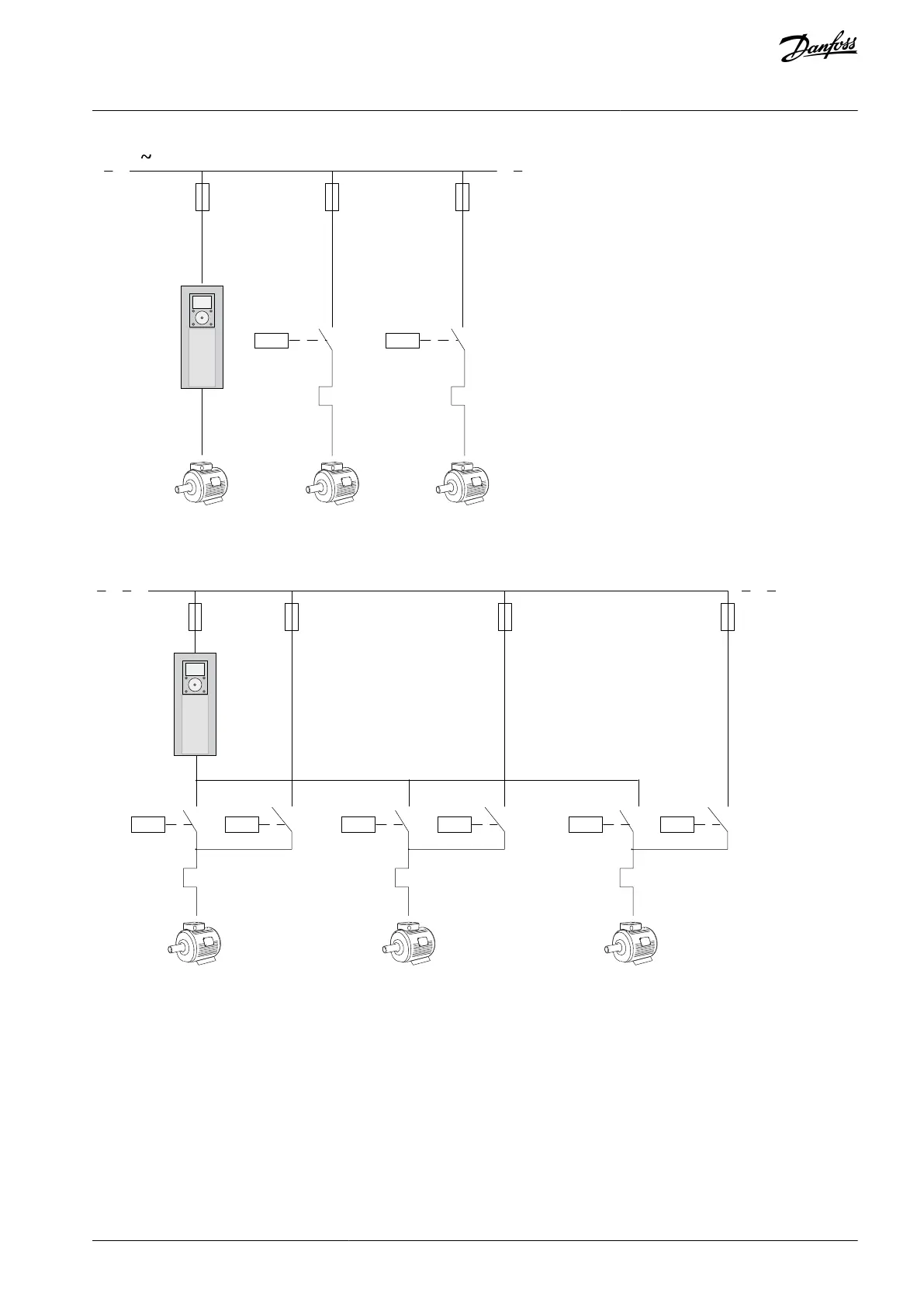
Illustration 11: Control Diagram with Only the Auxiliary Motors Configured to Autochange
K2.1 K3.1
M1 M2 M3
e30bi976.10
Illustration 12: Control Diagram with All the Motors Configured to Autochange
It is possible to use 2 control places. Make the selection of the control place A or B with DI6. When control place A is active, DI1 gives
the start and stop commands, and the PID controller gives the frequency reference. When control place B is active, DI4 gives the
start and stop commands, and AI1 gives the frequency reference.
It is possible to configure all the drive outputs freely in all the applications. There is 1 analog output (Output Frequency) and 3 relay
outputs (Run, Fault, Ready) available on the basic I/O board.
AB298035655957en-000201 / DPD01083 | 39Danfoss A/S © 2023.08
Applications
VACON® 100 FLOW
Application Guide

 Loading...

